ANTI-LOCK BRAKES
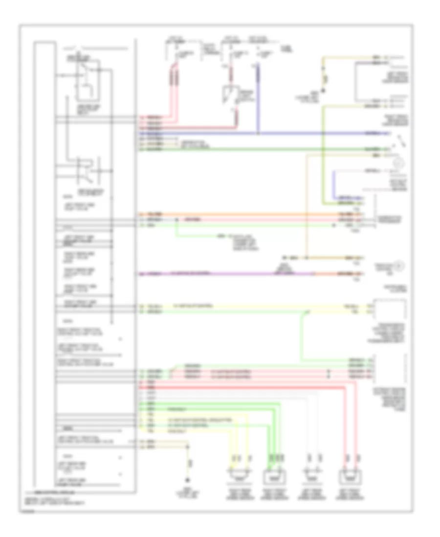
Anti-lock Brakes Wiring Diagram for Audi A4 Quattro 2000
List of elements for Anti-lock Brakes Wiring Diagram for Audi A4 Quattro 2000:
- (information not available)
- 13a
- 8-way relay carrier
- Abs control module
- Abs return flow pump
- Abs return flow pump relay
- Abs solenoid valve relay
- Abs/edl hydraulic unit (below left side of rear seat)
- All times
- Anti-slip control switch
- Brake- light switch
- Combination processor
- Data link connector (under left side of dash)
- Fuse 13 10a
- Fuse 53 60a
- Fuse 7 10a
- Fuse panel
- Fwd only
- G202 (behind left dash)
- G900 (lower left "a" pillar)
- Hot at
- Hot in on or start
- Instrument cluster
- Left front abs inlet valve
- Left front abs outlet valve
- Left front abs wheel speed sensor
- Left front brake pad wear sensor
- Left front traction control outlet valve
- Left front traction control switch-over valve
- Left rear abs inlet valve
- Left rear abs outlet valve
- Left rear abs wheel speed sensor
- Motronic engine control module (near brake booster in protective case)
- Red
- Right front abs inlet valve
- Right front abs outlet valve
- Right front abs wheel speed sensor
- Right front brake pad wear sensor
- Right front traction control outlet valve
- Right front traction control switch-over valve
- Right rear abs inlet valve
- Right rear abs outlet valve
- Right rear abs wheel speed sensor
- T32
- T32a
- Traction control ind
- Transmission control module (under carpet, forward of passenger's seat)
- W/ anti-slip control
- W/ anti-slip control or quattro
 English