ANTI-LOCK BRAKES
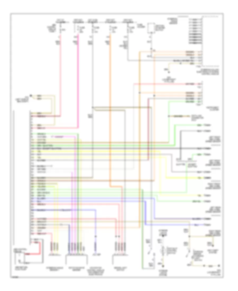
Anti-lock Brakes Wiring Diagram for Audi A4 Quattro 2002
List of elements for Anti-lock Brakes Wiring Diagram for Audi A4 Quattro 2002:
- (except quattro)
- (quattro)
- 13a
- 14a
- 42a
- 50a
- Abs control module
- Abs control module fuse 1
- Abs return flow pump
- Anti-slip control switch
- Anti-theft system
- Brake light switch
- Data link connector (dlc)
- Except quattro
- Fuse 10a
- Fuse 25a
- Fuse holder
- G12 (left side of eng compt)
- G43 (lower right "a" pillar)
- Hot at all times
- Hot in on or start
- Ignition/ starter switch
- Info not available
- Instrument cluster
- Interior lights system
- Left front abs wheel speed sensor
- Left rear abs wheel speed sensor
- Navigation control module for operating electronics
- Nca
- Parking brake warning light switch
- Quattro
- Red
- Right front abs wheel speed sensor
- Right rear abs wheel speed sensor
- Rotation rate sender
- Steering angle sensor
- Steering angle sensor 1
- Steering column electronic systems control module
- T16a
- T26
- T32
- T32a
 English