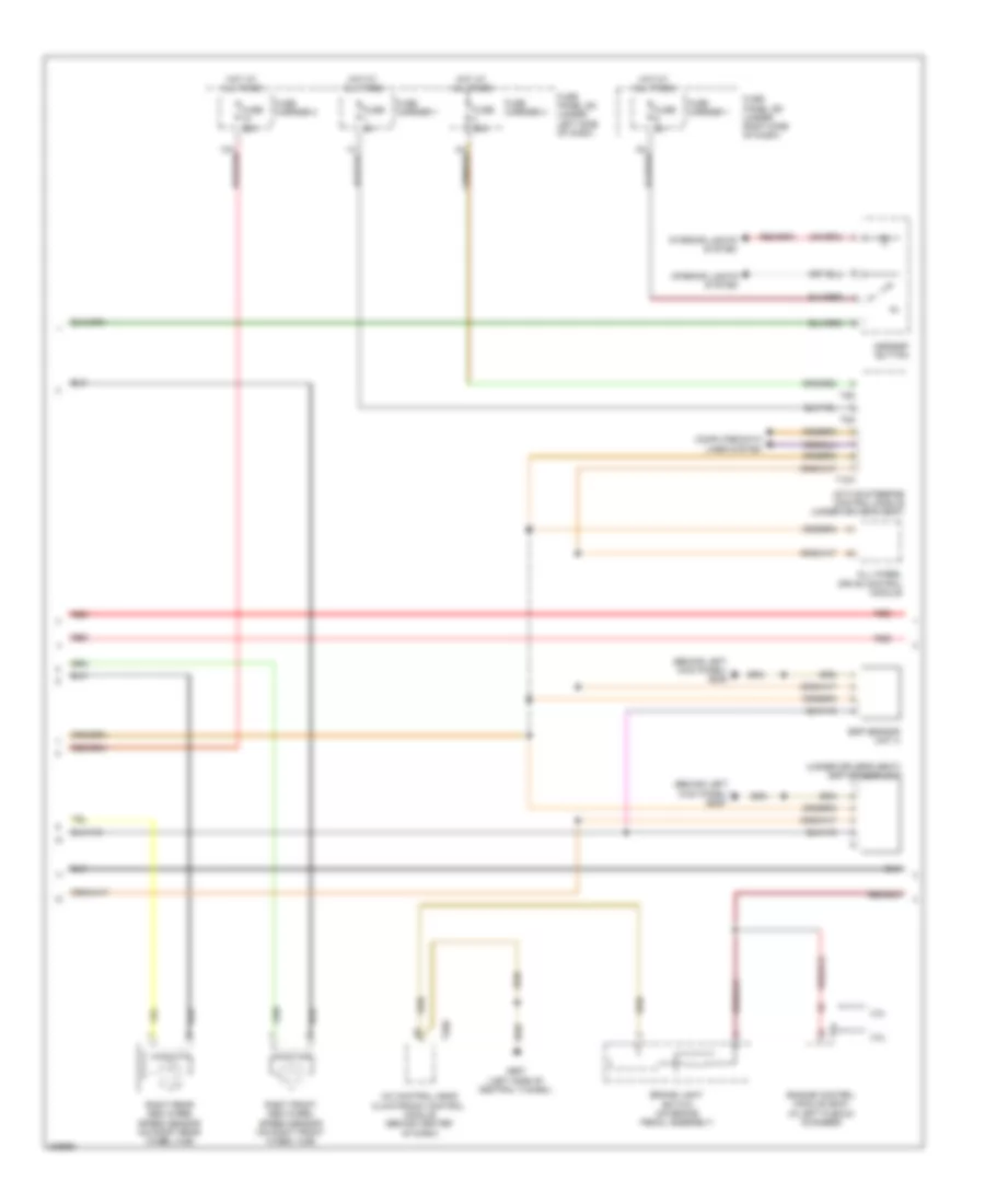
ANTI-LOCK BRAKES
Anti-lock Brakes Wiring Diagram (1 of 3) for Audi A5 Quattro 2009

List of elements for Anti-lock Brakes Wiring Diagram (1 of 3) for Audi A5 Quattro 2009:
- (17 pin connector)
- (left rear of engine compt) abs control module
- (on left front cross member)
- 40a
- Abs control module fuse 1
- Abs hydraulic pump
- Abs inlet left rear
- Abs outlet left rear
- Auto hold button
- Computer data lines system
- Driving dynamics regulation high pressure switch valve 2
- Electro-mechanical parking brake button
- Fuse 10a
- Fuse 110a
- Fuse 5a
- Fuse carrier 2
- Fuse carrier 4
- Fuse panel sc (under left side of dash)
- G671
- G671 (on left front cross member)
- Hot at all times
- Left front abs inlet valve
- Left front abs outlet valve
- Left front abs wheel speed sensor (on left front wheel hub)
- Left rear abs wheel speed sensor (on left rear wheel hub)
- Main fuse panel sa (on battery, in luggage compt)
- Red
- Regulation high driving dynamics
- Regulation switch driving dynamics
- Relay/fuse carrier luggage compartment sf (right side of luggage compt)
- Right front abs inlet valve
- Right front abs outlet valve
- Right rear abs inlet valve
- Right rear abs outlet valve
- T1zd
- Valve
- Valve 1
- Valve 1 pressure switch
- Valve 2
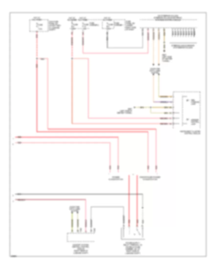
Anti-lock Brakes Wiring Diagram (2 of 3) for Audi A5 Quattro 2009
List of elements for Anti-lock Brakes Wiring Diagram (2 of 3) for Audi A5 Quattro 2009:
- (behind left
- (behind left kick panel) g639
- (under driver's seat) esp sensor unit
- 3.2l
- 4.2l
- A/c control head climatronic control module (behind center of dash)
- Active steering control module (under driver's seat)
- All wheel drive control module
- Asr/esp button
- Brake light switch (on brake pedal assembly)
- Computer data
- Engine control module (ecm) (in left plenum chamber)
- Esp sensor unit 2
- Fuse 25a
- Fuse 35a
- Fuse 5a
- Fuse carrier 1
- Fuse carrier 2
- Fuse carrier 3
- Fuse panel sc (under left side of dash)
- Fuse panel sd (under right side of dash)
- G687 (left side of central tunnel)
- Hot at all times
- Interior lights system
- Kick panel) g639
- Lines system
- Red
- Right front abs wheel speed sensor (on right front wheel hub)
- Right rear abs wheel speed sensor (on right rear wheel hub)
- T10h
- T20e
- T5d
- T8g
- T94
Anti-lock Brakes Wiring Diagram (3 of 3) for Audi A5 Quattro 2009
List of elements for Anti-lock Brakes Wiring Diagram (3 of 3) for Audi A5 Quattro 2009:
- (on steering column) steering column electronic systems control module
- 12a
- Abs warning lamp
- Asr/esp control lamp
- Comfort system central control module (right rear of luggage compt)
- Computer data lines system
- Discontinued phased in modification
- Fuse 110a
- Fuse 5a
- Fuse carrier 1
- Fuse carrier 2
- Fuse panel sd (under right side of dash)
- G687 (left side of center tunnel)
- Hot at all times
- Instrument cluster control module
- Main fuse panel sa (on battery, in luggage compt)
- Nca
- Phased in modification
- Red
- Steering angle sensor (in steering column)
- T32c
- T32d