ANTI-LOCK BRAKES
Anti-lock Brakes Wiring Diagram for Audi A6 2006
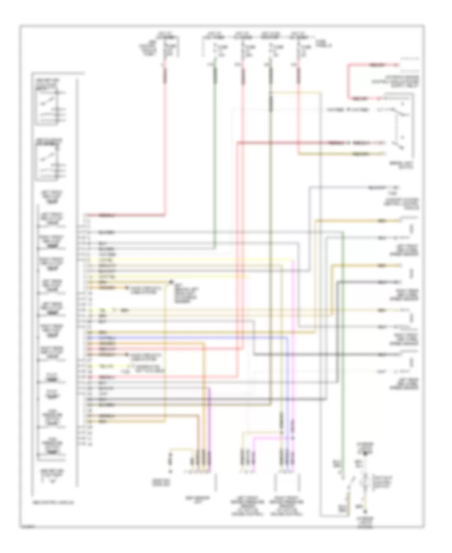
List of elements for Anti-lock Brakes Wiring Diagram for Audi A6 2006:
- (2005) g43 (2006) g33
- Abs control module
- Abs control module fuse 1
- Abs return flow pump
- Abs return flow pump relay
- Abs solenoid valve relay
- Anti-slip control switch
- Brake light switch
- Computer data lines system
- Confort system central control module
- Esp sensor unit
- Fuse 10a
- Fuse 25a
- Fuse 40a
- Fuse 5a
- Fuse panel b
- G671 (behind left headlight, on chassis member)
- High pressure switch valve 1
- High pressure switch valve 2
- Hot at all times
- Hot in on or start
- Information not available
- Interior lights system
- Left front abs inlet valve
- Left front abs outlet valve
- Left front abs wheel speed sensor
- Left front brake pressure sensor (w/ active cruise control)
- Left rear abs inlet valve
- Left rear abs outlet valve
- Left rear abs wheel speed sensor
- Pilot valve 1
- Pilot valve 2
- Right front abs inlet valve
- Right front abs outlet valve
- Right front abs wheel speed sensor
- Right front brake pressure sensor (w/ active cruise control)
- Right rear abs inlet valve
- Right rear abs outlet valve
- Right rear abs wheel speed sensor
- T10d
- T32d
 English