ANTI-LOCK BRAKES
Anti-lock Brakes Wiring Diagram (1 of 2) for Audi A8 L Quattro 2001

List of elements for Anti-lock Brakes Wiring Diagram (1 of 2) for Audi A8 L Quattro 2001:
- Abs control module (below left side of dash)
- Abs hydraulic unit (left front of engine compt)
- Abs outlet left front
- Abs return flow pump
- Abs return flow pump relay
- Abs solenoid valve relay
- Fuse 25a
- Fuse 60a
- G44 (above left kick panel)
- Hot at all times
- Left front abs inlet
- Left front abs wheel speed sensor
- Left rear
- Left rear abs wheel speed sensor
- Pilot valve 1 traction control
- Relay & fuse panel (right side of luggage compt)
- Relay panel (left side of dash, below driver's storage compt)
- Right front abs inlet valve
- Right front abs outlet
- Right front abs wheel speed sensor
- Right rear
- Right rear abs outlet
- Right rear abs wheel speed sensor
- Traction control high pressure switch valve 1
- Traction control high pressure switch valve 2
- Traction control hydraulic pump
- Traction control pilot valve 2
- Valve
- Valve abs inlet
- Valve abs outlet
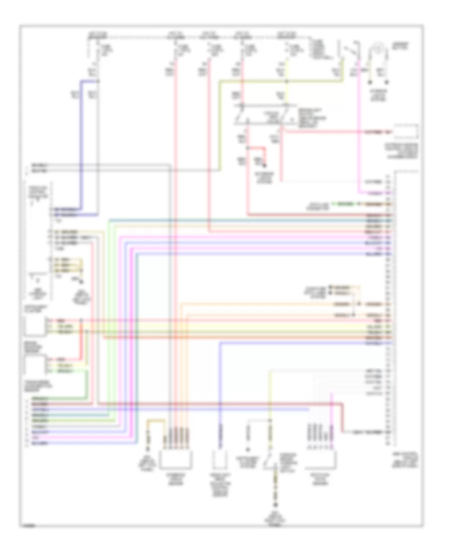
Anti-lock Brakes Wiring Diagram (2 of 2) for Audi A8 L Quattro 2001
List of elements for Anti-lock Brakes Wiring Diagram (2 of 2) for Audi A8 L Quattro 2001:
- (2001)
- 10a
- Abs control module (below left side of dash)
- Abs warning light
- Asr/esp button
- Brake booster sender
- Brakelight switch (above brake pedal, on bracket)
- Computer data lines system
- Data link connector
- Exterior lights system
- Fuse 1 (st3) 15a
- Fuse 10 (st4) 10a
- Fuse 7 (st2) 5a
- Fuse 9 (st2) 10a
- Fuse 9 (st4) 25a
- Fuse panel (right front footwell)
- G43 (above right kick panel)
- G44 (above
- G44 (above left kick panel)
- Headlight beam adjusting control module (2002-03)
- Hot at all times
- Hot in on or start
- Instrument cluster
- Instrument cluster system
- Interior lights system
- Left kick panel)
- Motronic engine control module (in plenum chamber e-box)
- Parking brake warning light switch
- Red
- Rotation rate sender
- Steering angle sensor
- T32
- T32b
- Traction control indicator
- Transverse acceleration sensor
- Vacuum vent valve