ANTI-LOCK BRAKES
Anti-lock Brakes Wiring Diagram (1 of 2) for Audi allroad Quattro 2005

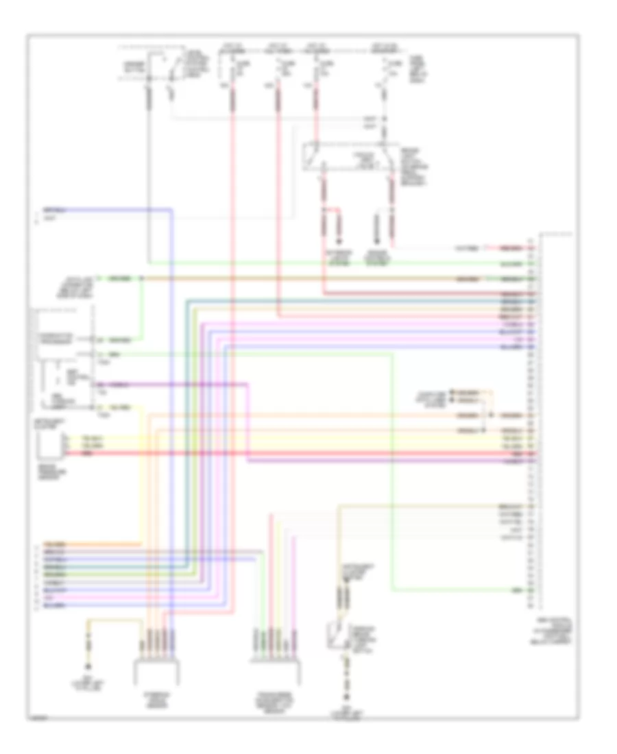
List of elements for Anti-lock Brakes Wiring Diagram (1 of 2) for Audi allroad Quattro 2005:
- 41a
- 8-fold relay panel (behind left side of dash)
- Abs control module (in passenger footwell, below carpet)
- Abs hydraulic unit (left side of engine compartment)
- Abs inlet left front
- Abs inlet left rear
- Abs outlet left front
- Abs outlet left rear
- Abs outlet right front
- Abs outlet right rear
- Abs return flow pump
- Abs return flow pump relay
- Abs solenoid valve relay
- Fuse 25a
- Fuse 50a
- Fuse panel (left end of dash)
- G100 (on abs hydraulic unit)
- Headlight beam adjusting control module
- Hot at all times
- Left front abs wheel speed sensor (mounted to left front wheel bearing housing)
- Left rear abs wheel speed sensor (mounted to left rear wheel bearing housing)
- Right front
- Right front abs wheel speed sensor (mounted to right front wheel bearing housing)
- Right rear abs inlet valve
- Right rear abs wheel speed sensor (mounted to right rear wheel bearing housing)
- Switch valve 2 high pressure
- Traction control
- Traction control high pressure switch valve 1
- Traction control hydraulic pump
- Traction control pilot valve 1
- Traction control pilot valve 2
- Valve
- Valve abs inlet
Anti-lock Brakes Wiring Diagram (2 of 2) for Audi allroad Quattro 2005
List of elements for Anti-lock Brakes Wiring Diagram (2 of 2) for Audi allroad Quattro 2005:
- Abs control module (in passenger footwell, below carpet)
- Abs warning light
- Asr/esp button
- Brake pressure sensor
- Brake- light switch (on brake pedal support bracket)
- Combination processor
- Computer data lines system
- Data link connector (below left side of dash)
- Engine controls system
- Esp control ind
- Exterior lights system
- Fuse 10a
- Fuse 25a
- Fuse 5a
- Fuse panel (left end of dash)
- G44 (lower left "a" pillar)
- Hot at all times
- Hot in on or start
- Instrument cluster
- Instrument cluster system
- Level control system control head
- Parking brake warning light switch
- Red
- Steering angle sensor
- T32
- T32a
- Transverse acceleration sensor/ yaw sensor
- Vacuum vent valve