
ANTI-LOCK BRAKES
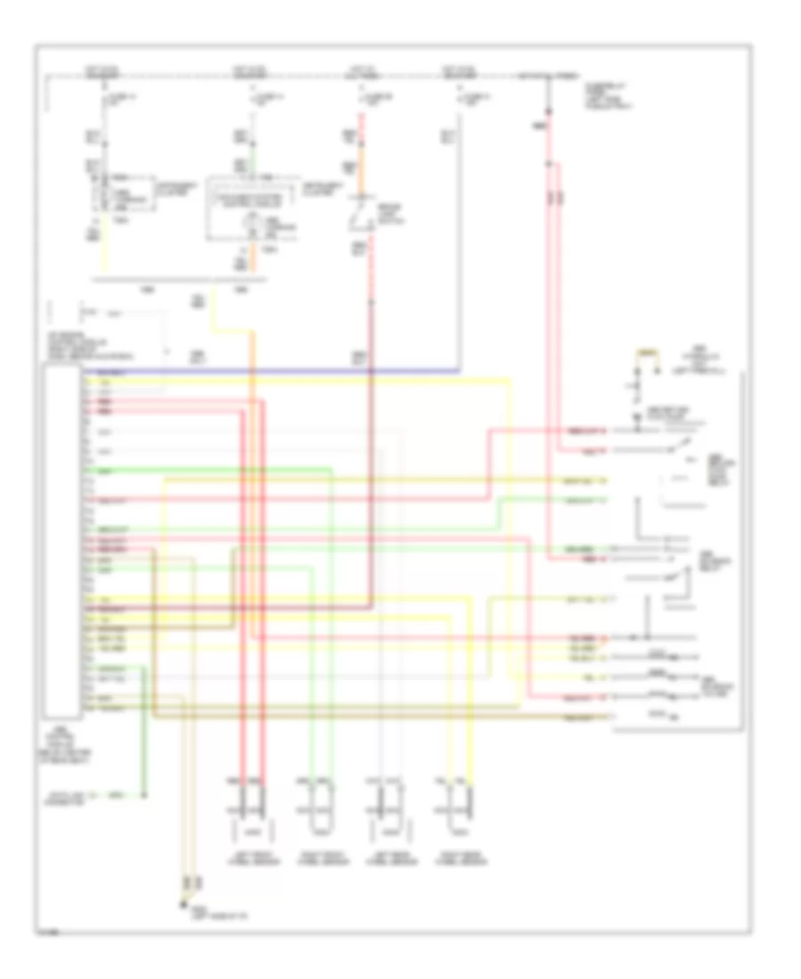
Anti-lock Brakes Wiring Diagram for Audi Cabriolet 1996
List of elements for Anti-lock Brakes Wiring Diagram for Audi Cabriolet 1996:
AIR CONDITIONINGANTI-LOCK BRAKESENGINE PERFORMANCEANTI-THEFTCOMPUTER DATA LINESCOOLING FANEXTERIOR LIGHTSDEFOGGERSCRUISE CONTROLGROUND DISTRIBUTIONINSTRUMENT CLUSTERINTERIOR LIGHTSHEADLIGHTSPOWER ANTENNAHORNPOWER DOOR LOCKSPOWER DISTRIBUTIONPOWER MIRRORSPOWER WINDOWSPOWER SEATSSHIFT INTERLOCKPOWER TOP/SUNROOFRADIOWARNING SYSTEMSTRANSMISSIONSTARTING/CHARGINGSUPPLEMENTAL RESTRAINTSWIPER/WASHER