ANTI-LOCK BRAKES
Anti-lock Brakes Wiring Diagram (1 of 2) for Audi Q7 Prestige 2014

List of elements for Anti-lock Brakes Wiring Diagram (1 of 2) for Audi Q7 Prestige 2014:
- Abs control module (abs hydraulic unit) (on abs hydraulic unit)
- Abs hydraulic pump
- Asr/esp button
- Brake booster membrane position sensor (w/ distance regulation) (on brake booster assembly)
- Brake pressure release solenoid & magnetic coil
- Comfort system central control module (right side of luggage compt)
- Computer data lines system
- Driving dynamics regulation high pressure switch valve 1
- Driving dynamics regulation high pressure switch valve 2
- Driving dynamics regulation switch valve 1
- Driving dynamics regulation switch valve 2
- Esp sensor unit (under center console)
- Fuse 20a
- Fuse 40a
- Fuse 5a
- Fuse carrier 1
- Fuse carrier 2
- Fuse panel c (right end of dash)
- G609 (right plenum chamber)
- G664 (behind left side of dash)
- Hot at all times
- Interior lights system
- Left front abs inlet valve
- Left front abs outlet valve
- Left front abs wheel speed sensor (left front wheel hub assembly)
- Left rear abs inlet valve
- Left rear abs outlet valve
- Left rear abs wheel speed sensor (left rear wheel hub assembly)
- Nca
- Red
- Relay & fuse carrier (center instrument panel) (center of dash)
- Right front abs inlet valve
- Right front abs outlet valve
- Right front abs wheel speed sensor (right front wheel hub assembly)
- Right rear abs inlet valve
- Right rear abs outlet valve
- Right rear abs wheel speed sensor (right rear wheel hub assembly)
- T12d
- T32d
- T4n
- T4o
- T4p
- T4q
- T6n
- T6o
- T6p
- T6q
- Tire pressure monitoring control module (behind left side of dash)
- Towing recognition control module (right side of luggage compt)
- W/ level control system
- W/o level control system
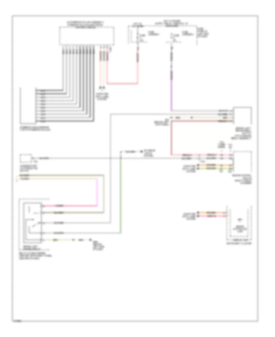
Anti-lock Brakes Wiring Diagram (2 of 2) for Audi Q7 Prestige 2014
List of elements for Anti-lock Brakes Wiring Diagram (2 of 2) for Audi Q7 Prestige 2014:
- (in steering column assembly) steering column electronic control module
- 11a
- 3.0l sc
- 3.0l turbo diesel
- Access/start authorization switch
- Brake light disable relay
- Brake light/ brake pedal switch (top of brake pedal assembly)
- Brake system ind lamp
- Computer data lines system
- Display unit
- Engine control module (right plenum chamber)
- Exterior lights system
- Fuse 10a
- Fuse 5a
- Fuse carrier 1
- Fuse carrier 3
- Fuse panel b (left end of dash)
- G44 (behind left kick panel)
- G664 (behind left side of dash)
- Hot at all times
- Instrument cluster
- Nca
- Relay & fuse carrier (center instrument panel) (center of dash)
- Steering angle sensor (top of steering column)
- T10c
- T16a
- T8a
- T91
- T94