ANTI-LOCK BRAKES
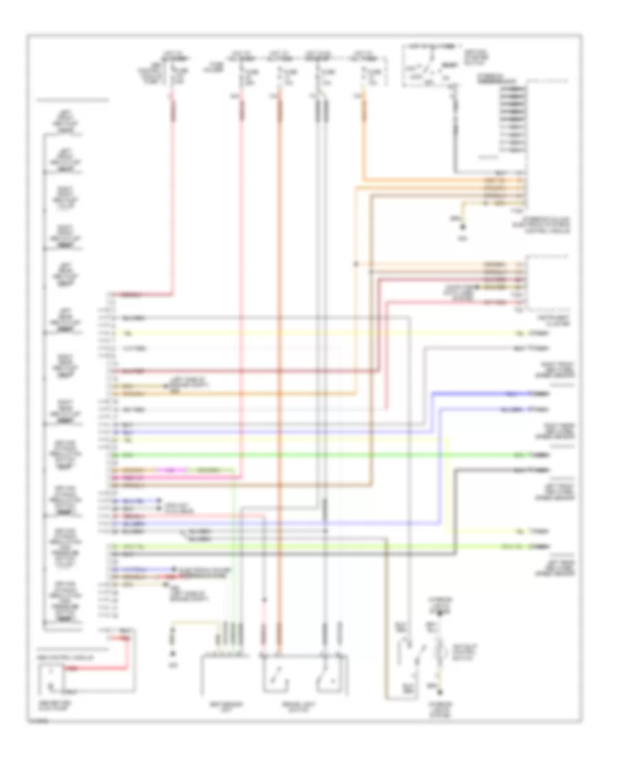
Anti-lock Brakes Wiring Diagram for Audi S4 Quattro 2006
List of elements for Anti-lock Brakes Wiring Diagram for Audi S4 Quattro 2006:
- (info not available)
- (left side of engine compt) g26
- Abs control module
- Abs control module fuse 1
- Abs return flow pump
- Acc
- Anti-slip control switch
- Brake light switch
- Computer data lines system
- Driving dynamic regulation high pressure switch valve 1
- Driving dynamic regulation high pressure switch valve 2
- Driving dynamic regulation switch valve 1
- Driving dynamic regulation switch valve 2
- Electronic power steering system
- Esp sensor unit
- Fuse 10a
- Fuse 25a
- Fuse 40a
- Fuse holder
- G26 (left side of engine compt)
- G33
- Hot at all times
- Hot in on or start
- Ignition/ starter switch start
- Instrument cluster
- Interior lights system
- Left front abs inlet valve
- Left front abs outlet valve
- Left front abs wheel speed sensor
- Left rear abs inlet valve
- Left rear abs outlet valve
- Left rear abs wheel speed sensor
- Lock
- Nca
- Off
- Red
- Right front abs inlet valve
- Right front abs outlet valve
- Right front abs wheel speed sensor
- Right rear abs inlet valve
- Right rear abs outlet valve
- Right rear abs wheel speed sensor
- Steering angle sensor
- Steering column electronic systems control module
- T16a
- T32
- T32a
 Русский