ANTI-LOCK BRAKES
Anti-lock Brakes Wiring Diagram (1 of 2) for Audi S8 2014

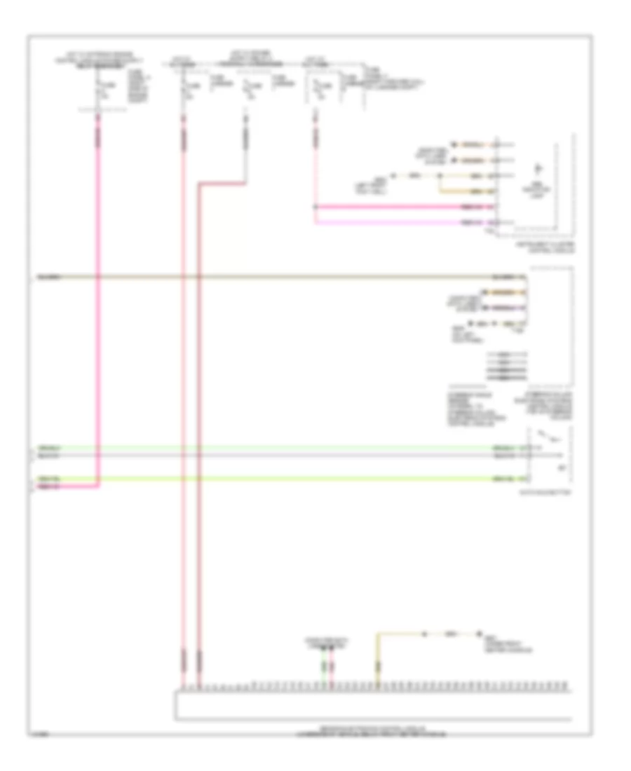
List of elements for Anti-lock Brakes Wiring Diagram (1 of 2) for Audi S8 2014:
- 10a
- 3.0l diesel
- 3.0l sc
- 4.0l turbo
- 50a
- 6.3l
- Abs control module (w/ edl: in left rear of plenum chamber)
- Abs control module fuse 1
- Abs hydraulic pump
- Asr/esp button
- Brake lamp switch (top of brake pedal assembly)
- Comfort system central control module (right forward wall of luggage compt)
- Computer data lines system
- Door locks system
- Driving dynamics regulation high pressure switch valve 1
- Driving dynamics regulation high pressure switch valve 2
- Driving dynamics regulation switch valve 1
- Driving dynamics regulation switch valve 2
- Engine control module (center rear of engine compt)
- Fuse 10a
- Fuse 25a
- Fuse 5a
- Fuse carrier
- Fuse panel b (right end of dash)
- Fuse panel f (right forward wall of luggage compt)
- G602 (left front foot well)
- G638 (on right kick panel)
- Hot at all times
- Interior lights system
- Left front abs inlet valve
- Left front abs outlet valve
- Left front abs wheel speed sensor (on left front wheel hub assembly)
- Left rear abs inlet valve
- Left rear abs outlet valve
- Left rear abs wheel speed sensor (on left rear wheel hub assembly)
- Pnk
- Red
- Right front abs inlet valve
- Right front abs outlet valve
- Right front abs wheel speed sensor (on right front wheel hub assembly)
- Right rear abs inlet valve
- Right rear abs outlet valve
- Right rear abs wheel speed sensor (on right rear wheel hub assembly)
- T17f
- T17g
- T17i
- T17k
- T32c
- T32d
- T91
- T94
Anti-lock Brakes Wiring Diagram (2 of 2) for Audi S8 2014
List of elements for Anti-lock Brakes Wiring Diagram (2 of 2) for Audi S8 2014:
- Abs indicator lamp
- Auto hold button
- Computer data lines system
- Fuse 5a
- Fuse carrier
- Fuse panel a (right side of engine compt)
- Fuse panel f (right forward wall of luggage compt)
- G602 (left front foot well)
- G639 (on left kick panel)
- G687 (under front center console)
- Hot at all times
- Instrument cluster control module
- Nca
- Pnk
- Sensor electronics control module (underside of vehicle, below front center console)
- Steering angle sensor (integral to steering column electronic systems control module)
- Steering column electronic systems control module (top of steering column)
- T16d
- T32