ANTI-LOCK BRAKES
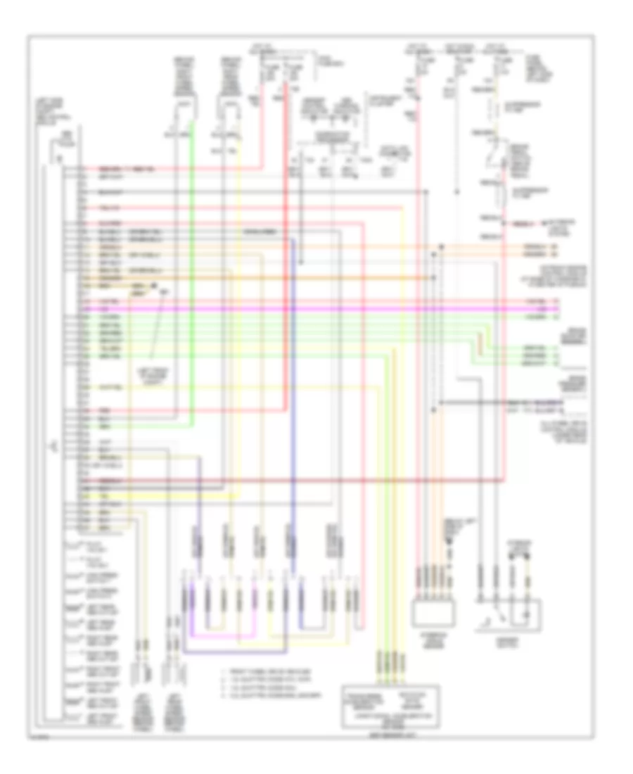
Anti-lock Brakes Wiring Diagram for Audi TT 2006
List of elements for Anti-lock Brakes Wiring Diagram for Audi TT 2006:
- (behind wheel) right front wheel speed sensor
- (behind wheel) right rear wheel speed sensor
- (below left side of dash) g42
- (left front of engine compt)
- (left side of engine compt) abs control module
- 1.8l quattro (code amu)
- 1.8l quattro (code atc, awp)
- 13a
- 15a
- 3.2l quattro (code bhe, 2005 bpf)
- Abs hyd pump
- Abs warning indicator
- All-wheel drive control module (under rear of vehicle)
- Asr/esp control indicator
- Asr/esp switch
- Brake booster sender 1
- Brake pedal switch (above brake pedal)
- Brake pressure sensor 2
- Combination processor
- Data link connector
- Esp sensor unit
- Exterior lights system
- Front wheel drive vehicles
- Fuse 10a
- Fuse 30a
- Fuse 5a
- Fuse panel (behind left side of dash)
- G12
- High press switch 1
- High press switch 2
- Hot at all times
- Hot in run or start
- Instrument cluster
- Interior lights system
- Left front abs inlet
- Left front abs outlet
- Left front wheel speed sensor (behind wheel)
- Left rear abs inlet
- Left rear abs outlet
- Left rear wheel speed sensor (behind wheel)
- Longitudinal acceleration sensor (w/ awd)
- Main fuse box
- Motronic engine control module (at base of windsheild, in center of plenum)
- Pilot valve 1
- Pilot valve 2
- Red
- Right front abs inlet
- Right front abs outlet
- Right rear abs inlet
- Right rear abs outlet
- Rotation rate sender
- Steering angle sensor
- Suppressor filter
- T16
- T32
- T32a
- T3e
- Transverse acceleration sensor
 English