ANTI-LOCK BRAKES
Anti-lock Brakes Wiring Diagram, with Electronic Stability Program for Audi TT Quattro 2001
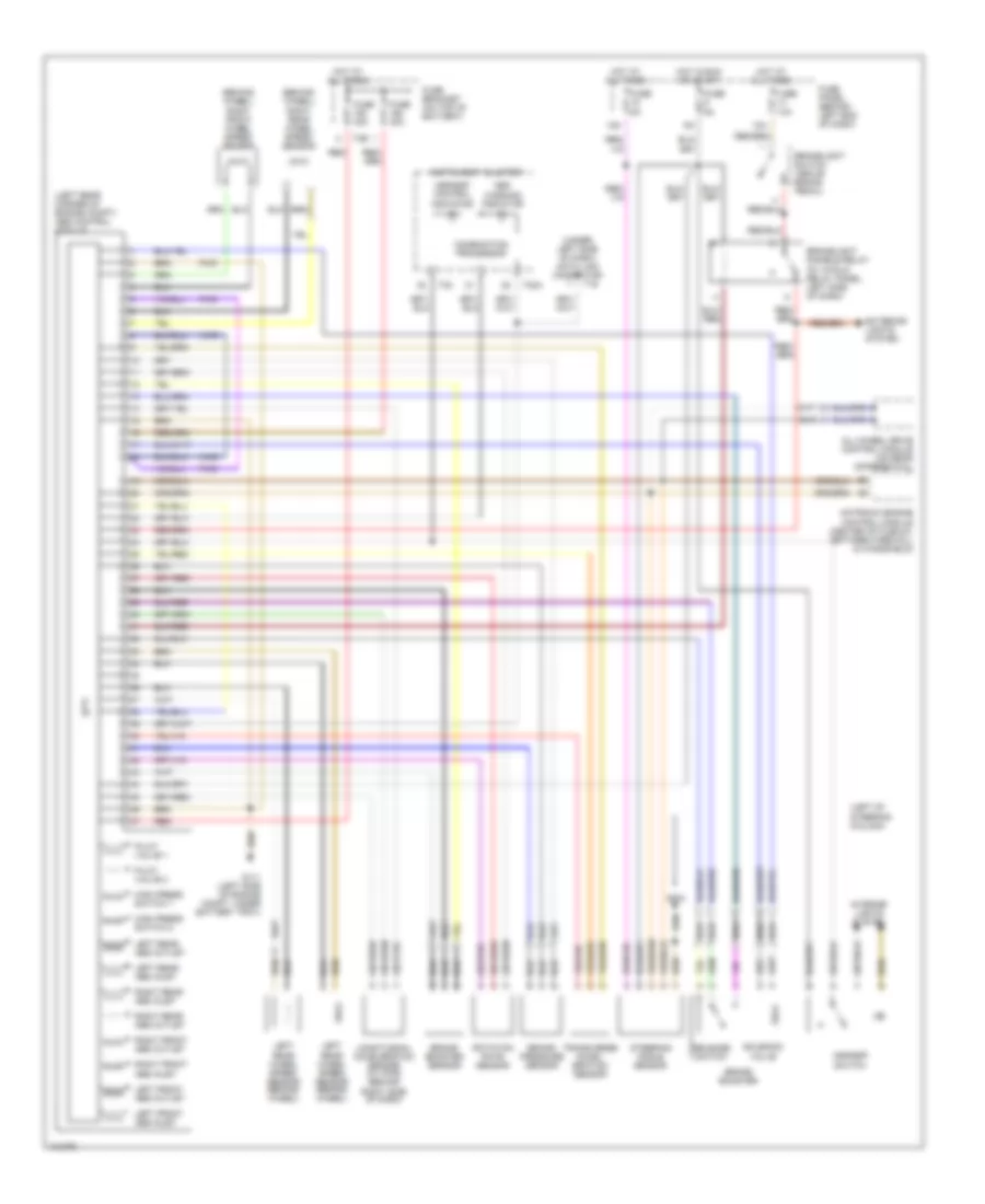
List of elements for Anti-lock Brakes Wiring Diagram, with Electronic Stability Program for Audi TT Quattro 2001:
- (behind wheel) right front wheel speed sensor
- (behind wheel) right rear wheel speed sensor
- (left of steering column)
- (left rear corner of engine compt) abs control module
- (under left side of dash) data link connector
- 13a
- 15a
- Abs warning indicator
- All-wheel drive control module (on rear differential)
- Asr/esp control indicator
- Asr/esp switch
- Awd
- Brake booster
- Brake booster sensor
- Brake pressure sensor
- Brakelight disable relay (in 13-fold relay panel, left side of dash)
- Brakelight switch (above brake pedal)
- Combination processor
- Exterior lights system
- Fuse 10a
- Fuse 30a
- Fuse 5a
- Fuse bracket (on top of battery)
- Fuse panel (behind left end of dash)
- Fwd
- G111 (left side of engine compt, under battery tray)
- G204
- High press switch 1
- High press switch 2
- Hot at all times
- Hot in run or start
- Instrument cluster
- Interior lights system
- Left front abs inlet
- Left front abs outlet
- Left rear abs inlet
- Left rear abs outlet
- Left rear wheel speed sensor (behind wheel)
- Longitudinal acceleration sensor (w/ awd) (behind right side of dash)
- Motronic engine control module (center of plenum, between firewall & windshield)
- Pilot valve 1
- Pilot valve 2
- Red
- Release switch
- Right front abs inlet
- Right front abs outlet
- Right rear abs inlet
- Right rear abs outlet
- Rotation rate sensor
- Solenoid valve
- Steering angle sensor
- T16
- T32
- T32a
- T3e
- Transverse accel- eration sensor
 English