ANTI-LOCK BRAKES
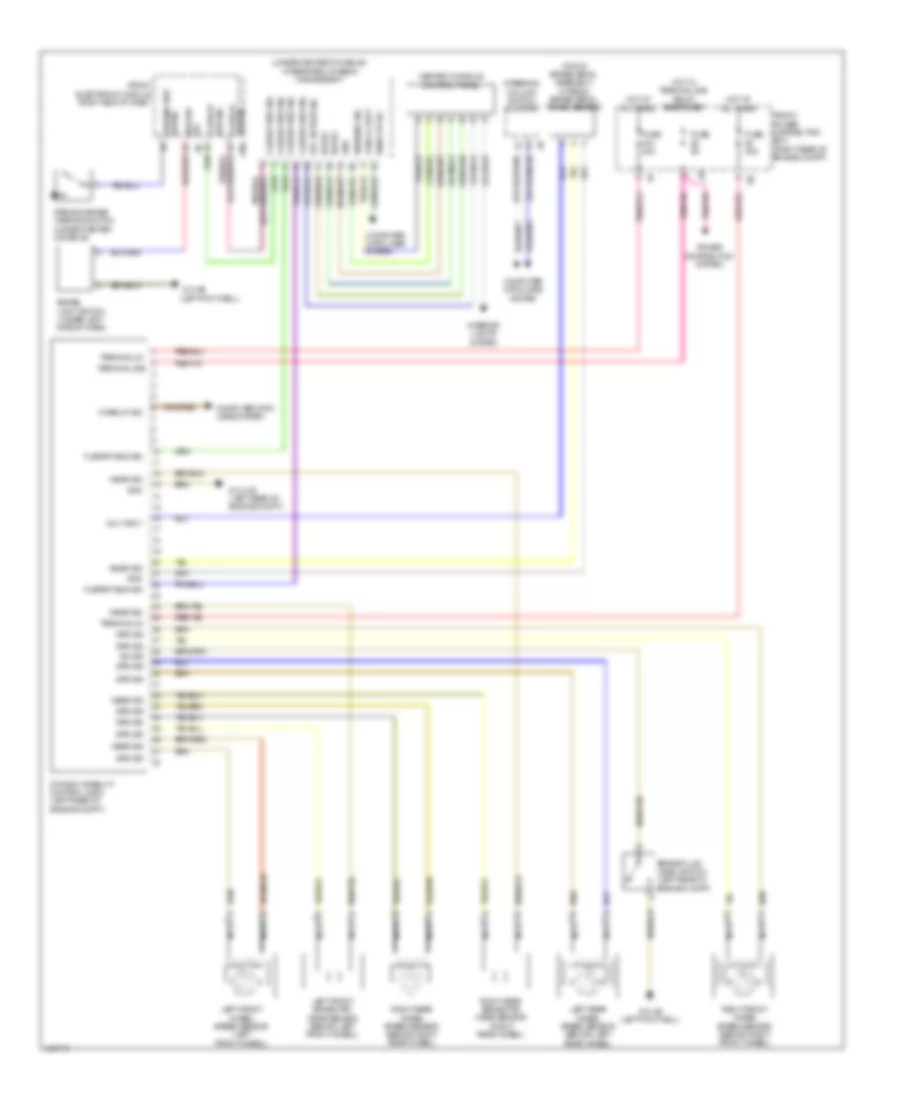
Anti-lock Brakes Wiring Diagram for BMW 320i 2014
List of elements for Anti-lock Brakes Wiring Diagram for BMW 320i 2014:
- (top of brake pedal assembly) (hybrid) brake pedal travel sensor
- (under center console) integrated chassis management
- Brake fluid level switch (left rear of engine compt)
- Brake light switch (under left side of dash)
- Bus sig flexray
- Center console control panel
- Computer data lines system
- Distribution system
- Dtc button sig
- Dynamic stability control (dsc) (left rear of engine compt)
- Flexray bus sig
- Front electronic module (right end of dash)
- Front power distribution box (right rear of engine compt)
- Funch light
- Fuse 30a
- Fuse 40a
- Fuse 5a
- Gnd
- Hot at all times
- Hot w/ terminal 30b relay energized
- Interior lights system
- Left front brake pad wear sensor (behind left front wheel)
- Left front wheel speed sensor (left front wheel)
- Left rear wheel speed sensor (behind left rear wheel)
- Nca
- Parking brake warning switch (under center console)
- Power
- Right front wheel speed sensor (behind right front wheel)
- Right rear brake pad wear sensor (right rear wheel)
- Right rear wheel speed sensor (behind right rear wheel)
- Sig brk sw
- Snsr sig
- Spd sig
- Steering column switch cluster
- Sw sig
- Sw sig parking brk
- Terminal 30
- Terminal 30b
- Volt sply
- Wake up sig
- Warning sig
- Wear sig
- Z10 21b (left rear of engine compt)
- Z10 4b (left footwell)
 English