ANTI-LOCK BRAKES
Anti-lock Brakes Wiring Diagram for BMW 320xi 2013
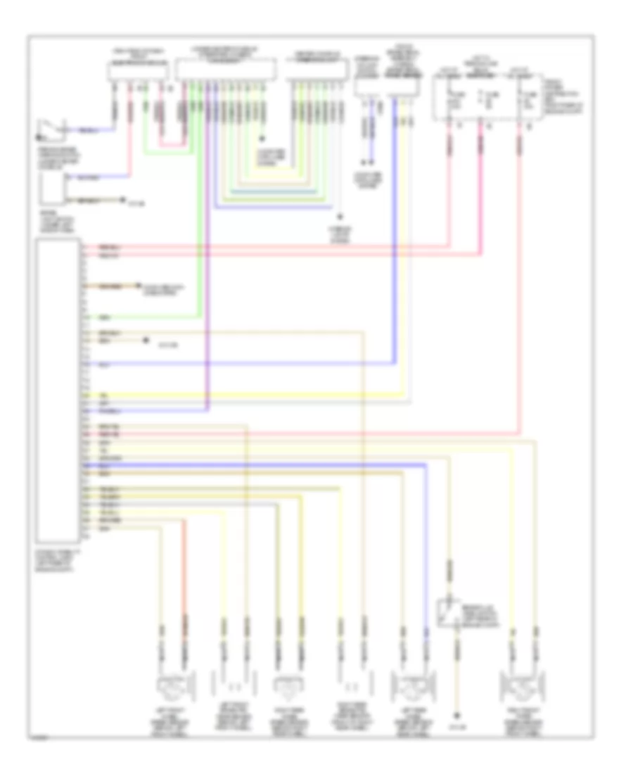
List of elements for Anti-lock Brakes Wiring Diagram for BMW 320xi 2013:
- (right end of dash) front electronic module
- (top of brake pedal assembly) (hybrid) brake pedal travel sensor
- (under center console) integrated chassis management
- Brake fluid level switch (left rear of engine compt)
- Brake light switch (under left side of dash)
- Center console operating unit
- Computer data lines system
- Dynamic stability control (dsc) (left rear of engine compt)
- Front power distribution box (right rear of engine compt)
- Fuse 30a
- Fuse 40a
- Fuse 5a
- Hot at all times
- Hot w/ terminal 30b relay energized
- Interior lights system
- Left front brake pad wear sensor (behind left front wheel)
- Left front wheel speed sensor (behind left front wheel)
- Left rear wheel speed sensor (behind left rear wheel)
- Nca
- Parking brake warning switch (under center console)
- Right front wheel speed sensor (behind right front wheel)
- Right rear brake pad wear sensor (front of right rear wheel)
- Right rear wheel speed sensor (behind right rear wheel)
- Steering column switch cluster
- X1880
- Z10 21b
- Z10 4b
 English