ANTI-LOCK BRAKES
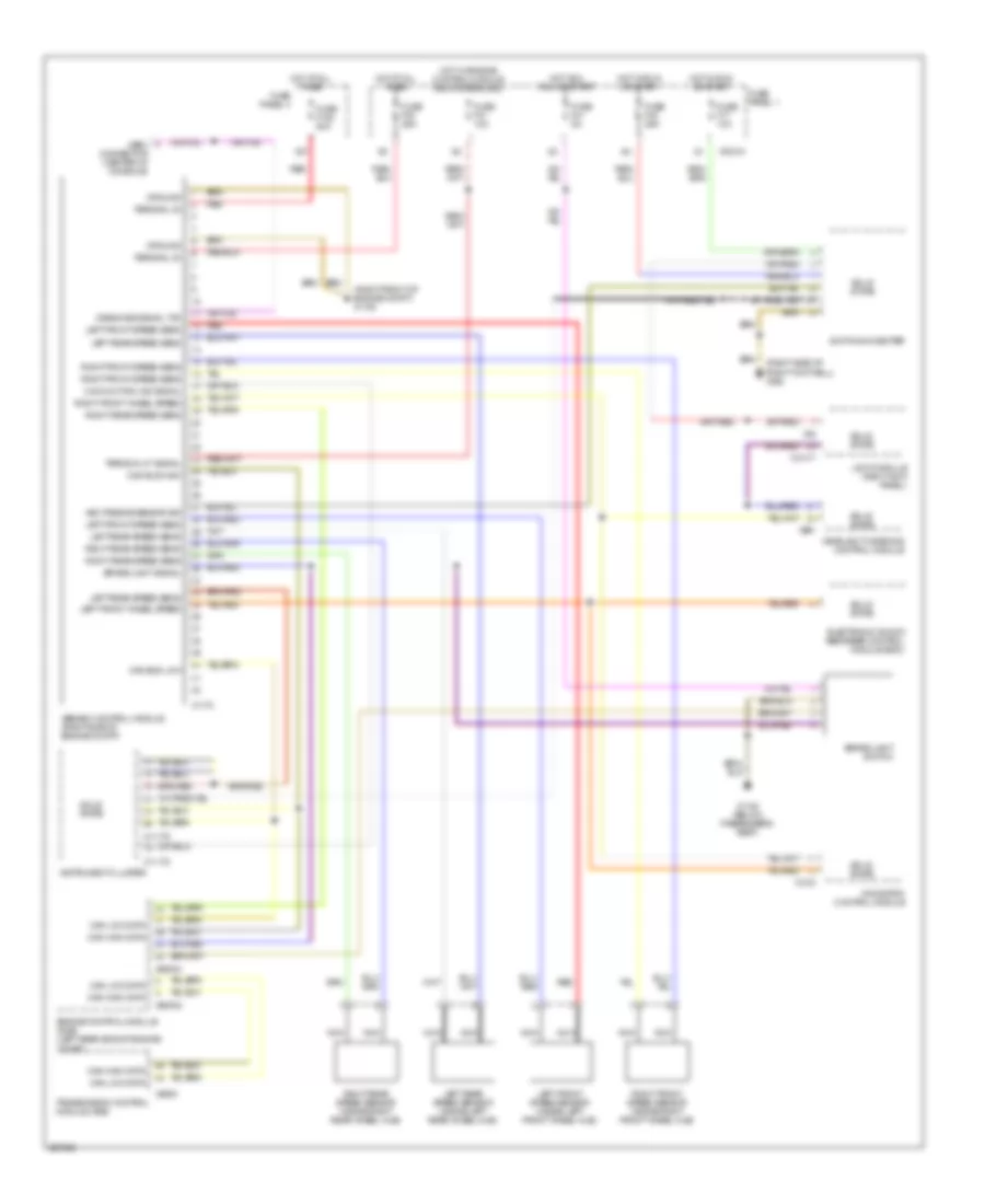
Anti-lock Brakes Wiring Diagram, with Automatic Stability Control, with IKE for BMW 530i 2001

List of elements for Anti-lock Brakes Wiring Diagram, with Automatic Stability Control, with IKE for BMW 530i 2001:
- (right front of engine compt) x1106
- (right side of right footwell) x492
- Abs/asc control module (right side of engine compt)
- Asc passive sensor sig
- Brake light signal
- Brake light switch
- Can bus high
- Can bus low
- Can high data
- Can low data
- Diagnosis signal txd
- Electronic shock absorber control module (edc)
- Engine control module (dme) (left rear side of engine compt)
- Fuse f108 50a
- Fuse f17 10a
- Fuse f30 25a
- Fuse f32 25a
- Fuse f41 5a
- Fuse panel 1
- Fuse panel 4
- Ground
- Headlight widening control module
- Hot acc, run or start
- Hot at all times
- Hot in run or start
- Instrument cluster
- Integrated instrument cluster control module
- Left front speed sens
- Left front speed sensor (inside left front wheel hub)
- Left front wheel speed
- Left rear speed sens
- Left rear speed sensor (inside left rear wheel hub)
- Light module (right kick panel)
- Malfunction ind signal
- Navigation control module
- Nca
- Odbii connector (center of console)
- Red
- Right front speed sens
- Right front speed sensor (inside right front wheel hub)
- Right front wheel speed
- Right rear speed sens
- Right rear speed sensor (inside right rear wheel hub)
- Solid state
- Switching center
- Terminal 15 signal
- Terminal 30
- Transmission control module (ags)
- X10015
- X10113
- X10114
- X10117
- X1108 (below passenger's seat)
- X1170
- X1312
- X16
- X27
- X38
- X60002
- X60004
- X8600
- X991
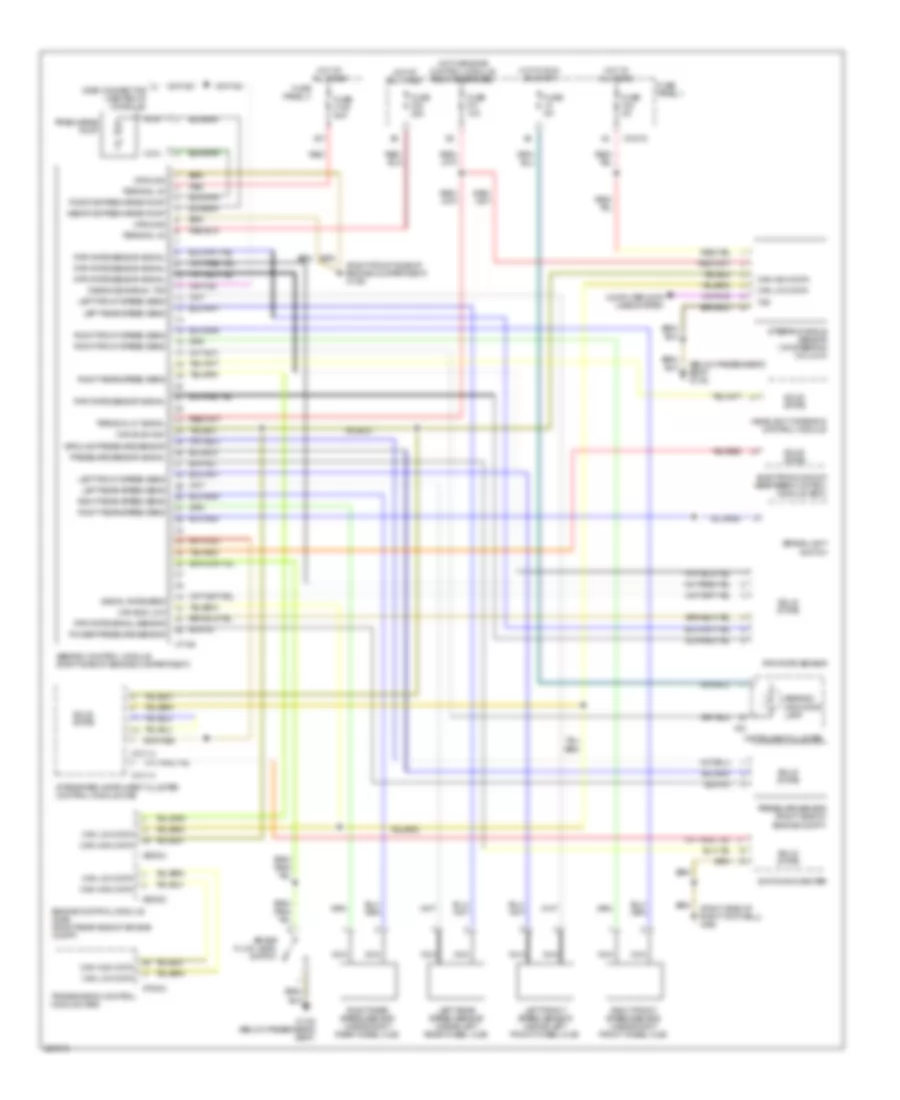
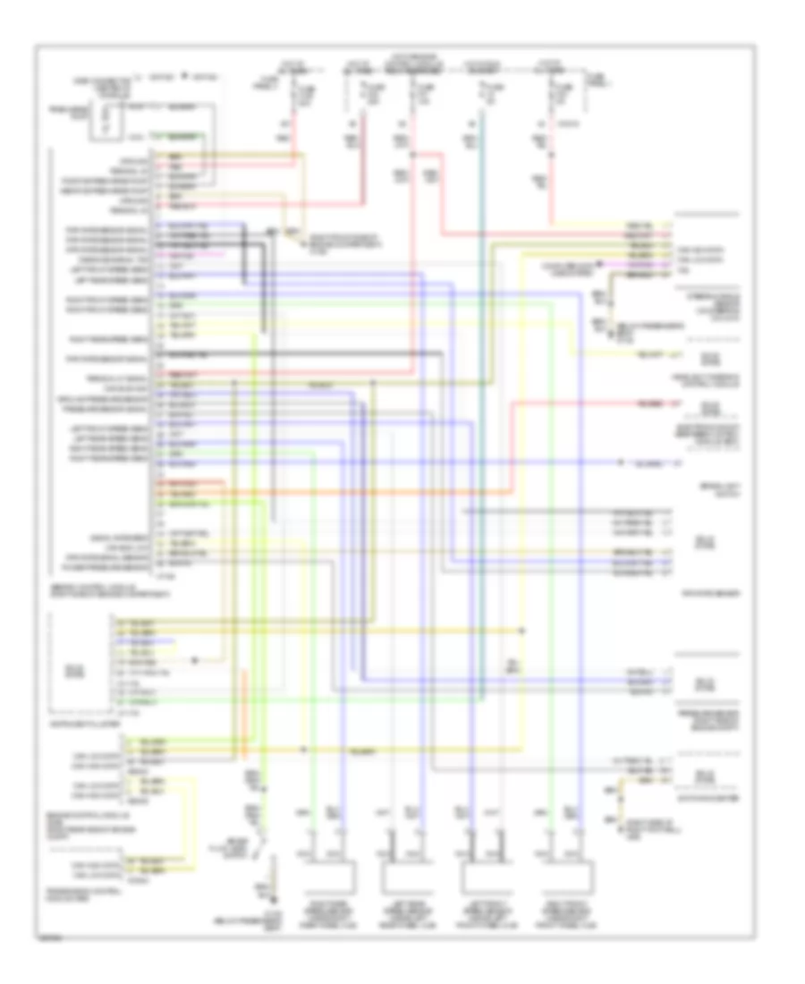
Anti-lock Brakes Wiring Diagram, with Automatic Stability Control, without IKE for BMW 530i 2001
List of elements for Anti-lock Brakes Wiring Diagram, with Automatic Stability Control, without IKE for BMW 530i 2001:
- (right front of engine compt) x1106
- (right side of right footwell) x492
- Abs/asc control module (right side of engine compt)
- Asc passive sensor sig
- Brake light signal
- Brake light switch
- Can bus high
- Can bus low
- Can high data
- Can low data
- Diagnosis signal txd
- Electronic shock absorber control module (edc)
- Engine control module (dme) (left rear side of engine compt)
- Fuse f108 50a
- Fuse f17 10a
- Fuse f30 25a
- Fuse f31 10a
- Fuse f32 25a
- Fuse f41 5a
- Fuse panel 1
- Fuse panel 4
- Ground
- Headlight widening control module
- Hot acc, run or start
- Hot at all times
- Hot in run or start
- Hot w/ engine control module relay energized
- Instrument cluster
- Left front speed sens
- Left front speed sensor (inside left front wheel hub)
- Left front wheel speed
- Left rear speed sens
- Left rear speed sensor (inside left rear wheel hub)
- Light module (right kick panel)
- Malfunction ind signal
- Navigation control module
- Nca
- Obdii connector (center of console)
- Red
- Right front speed sens
- Right front speed sensor (inside right front wheel hub)
- Right front wheel speed
- Right rear speed sens
- Right rear speed sensor (inside right rear wheel hub)
- Solid state
- Switching center
- Terminal 30
- Terminal 87 signal
- Transmission control module (ags)
- X10015
- X10117
- X1108 (below passenger's seat)
- X11175
- X11176
- X1170
- X1312
- X27
- X38
- X60002
- X60004
- X8600
- X991
Anti-lock Brakes Wiring Diagram, with Dynamic Stability Control, with IKE for BMW 530i 2001
List of elements for Anti-lock Brakes Wiring Diagram, with Dynamic Stability Control, with IKE for BMW 530i 2001:
- (below passenger's seat) x1108
- (right front side of engine compartment) x1106
- (right side of right footwell) x492
- Abs/dsc control module (right side of engine compartment)
- Abs/dsc indicator lamp
- Brake fluid level switch
- Brake light switch
- Can bus high
- Can bus low
- Can high data
- Can low data
- Computer data lines system
- Diagnosis signal txd
- Electronic shock absorber control module (edc)
- Engine control module (dme) (right rear side of engine compt)
- Fuse 5a
- Fuse f108 50a
- Fuse f24 5a
- Fuse f30 25a
- Fuse f31 10a
- Fuse panel 1
- Fuse panel 4
- Ground
- Ground pressure sensor
- Headlight widening control module
- Hot at all times
- Hot in run or start
- Hot w/engine control module relay energized
- Instrument cluster
- Integrated instrument cluster control module (ike)
- Left front speed sens
- Left front speed sensor (inside left front wheel hub)
- Left rear speed sens
- Left rear speed sensor (inside left rear wheel hub)
- Nca
- Odbii connector (center of console)
- Positive precharge pump
- Power pressure sensor
- Precharge pump
- Pressure sensor (right side of engine compt)
- Pressure sensor signal
- Red
- Right front speed sens
- Right front speed sensor (inside right front wheel hub)
- Right rear speed sens
- Right rear speed sensor (inside right rear wheel hub)
- Rpm rate sensor
- Rpm rate sensor signal
- Rpm rate signal sensor
- Signal rate sens
- Solid state
- Steering angle sensor (on steering column)
- Switching center
- Terminal 30
- Terminal 87 signal
- Transmission control module (ags)
- Txd
- X10015
- X10113
- X10114
- X1108 (below passenger's seat)
- X16
- X1746
- X27
- X60002
- X60004
- X70004
Anti-lock Brakes Wiring Diagram, with Dynamic Stability Control, without IKE for BMW 530i 2001
List of elements for Anti-lock Brakes Wiring Diagram, with Dynamic Stability Control, without IKE for BMW 530i 2001:
- (below passenger's seat) x1108
- (right front side of engine compartment) x1106
- (right side of right footwell) x492
- Abs/dsc control module (right side of engine compartment)
- Brake fluid level switch
- Brake light switch
- Can bus high
- Can bus low
- Can high data
- Can low data
- Computer data lines system
- Diagnosis signal txd
- Electronic shock absorber control module (edc)
- Engine control module (dme) (right rear side of engine compt)
- Fuse 5a
- Fuse f108 50a
- Fuse f24 5a
- Fuse f30 25a
- Fuse f31 10a
- Fuse panel 1
- Fuse panel 4
- Ground
- Ground pressure sensor
- Headlight widening control module
- Hot at all times
- Hot in run or start
- Hot w/engine control module relay energized
- Instrument cluster
- Left front speed sens
- Left front speed sensor (inside left front wheel hub)
- Left rear speed sens
- Left rear speed sensor (inside left rear wheel hub)
- Nca
- Odbii connector (center of console)
- Positive precharge pump
- Power pressure sensor
- Precharge pump
- Pressure sensor (right side of engine compt)
- Pressure sensor signal
- Red
- Right front speed sens
- Right front speed sensor (inside right front wheel hub)
- Right rear speed sens
- Right rear speed sensor (inside right rear wheel hub)
- Rpm rate sensor
- Rpm rate sensor signal
- Rpm rate signal sensor
- Signal rate sens
- Solid state
- Steering angle sensor (on steering column)
- Switching center
- Terminal 30
- Terminal 87 signal
- Transmission control module (ags)
- Txd
- X10015
- X1108 (below passenger's seat)
- X11175
- X11176
- X1746
- X27
- X60002
- X60004
- X70004