ANTI-LOCK BRAKES
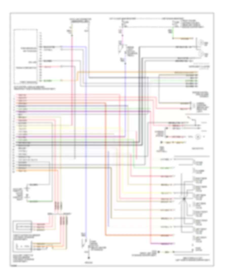
Anti-lock Brake Wiring Diagrams (1 of 2) for BMW 530iT 1994

List of elements for Anti-lock Brake Wiring Diagrams (1 of 2) for BMW 530iT 1994:
Anti-lock Brake Wiring Diagrams (2 of 2) for BMW 530iT 1994
List of elements for Anti-lock Brake Wiring Diagrams (2 of 2) for BMW 530iT 1994: