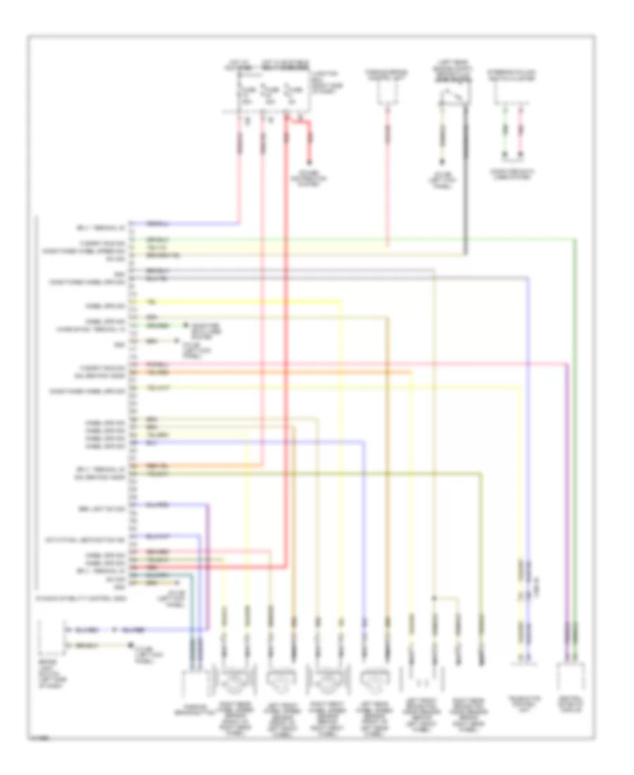
ANTI-LOCK BRAKES
Anti-lock Brakes Wiring Diagram for BMW 535i GT 2010
List of elements for Anti-lock Brakes Wiring Diagram for BMW 535i GT 2010:
- (left rear engine compt) brake fluid level switch
- 13b
- Activation, led function ind
- Brake light switch (left side of dash)
- Brk light sw sig
- Central gateway module
- Computer data lines system
- Conditioned wheel spd sig
- Conditioned wheel speed sig
- Dynamic stability control (dsc)
- Flexray bus sig
- Fuse 30a
- Fuse 50a
- Fuse 5a
- Gnd
- Hot at all times
- Hot w/ bi-stable relay energized
- Junction box (right side of dash)
- Left front brake pad wear sensor (behind left front wheel)
- Left front wheel speed sensor (front of left front wheel)
- Left rear wheel speed sensor (front of left rear wheel)
- Nca
- Parking brake button
- Parking brake control unit
- Pnk
- Power distribution system
- Red
- Right front wheel speed sensor (behind right front wheel)
- Right rear brake pad wear sensor (behind right rear wheel)
- Right rear wheel speed sensor (front of right rear wheel)
- Sig, brk pad wear
- Sply, terminal 30
- Steering column switch cluster
- Sw sig
- Telematics control unit
- Wake-up sig, terminal 15
- Wheel spd sig
- X188 1b
- Z10 4b (left kick panel)
- Z10 9b (left kick panel)
 English