ANTI-LOCK BRAKES
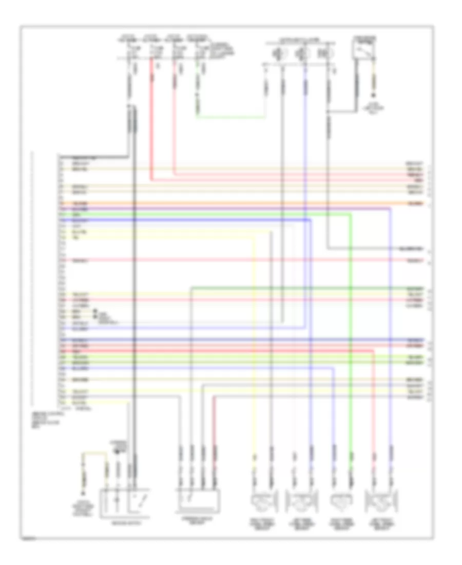
Anti-lock Brakes Wiring Diagram, with Dynamic Stability Control III (1 of 2) for BMW 750iL 1998

List of elements for Anti-lock Brakes Wiring Diagram, with Dynamic Stability Control III (1 of 2) for BMW 750iL 1998:
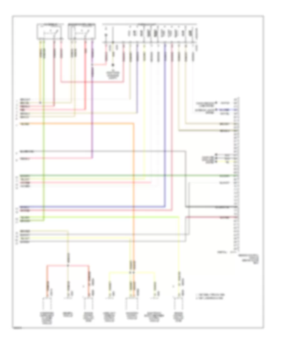
Anti-lock Brakes Wiring Diagram, with Dynamic Stability Control III (2 of 2) for BMW 750iL 1998
List of elements for Anti-lock Brakes Wiring Diagram, with Dynamic Stability Control III (2 of 2) for BMW 750iL 1998:
Anti-lock Brakes Wiring Diagram, with Dynamic Stability Control (1 of 2) for BMW 750iL 1998
List of elements for Anti-lock Brakes Wiring Diagram, with Dynamic Stability Control (1 of 2) for BMW 750iL 1998:
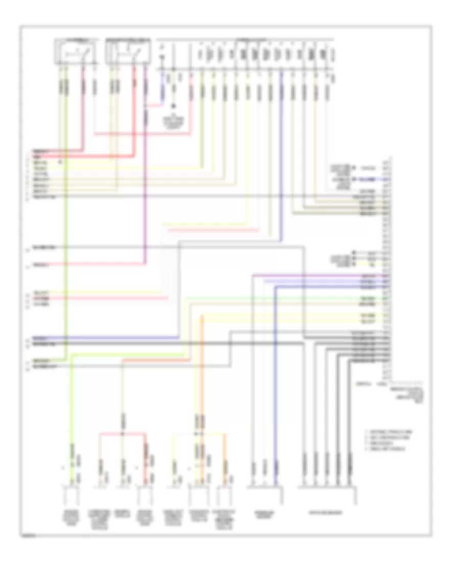
Anti-lock Brakes Wiring Diagram, with Dynamic Stability Control (2 of 2) for BMW 750iL 1998
List of elements for Anti-lock Brakes Wiring Diagram, with Dynamic Stability Control (2 of 2) for BMW 750iL 1998: