ANTI-LOCK BRAKES
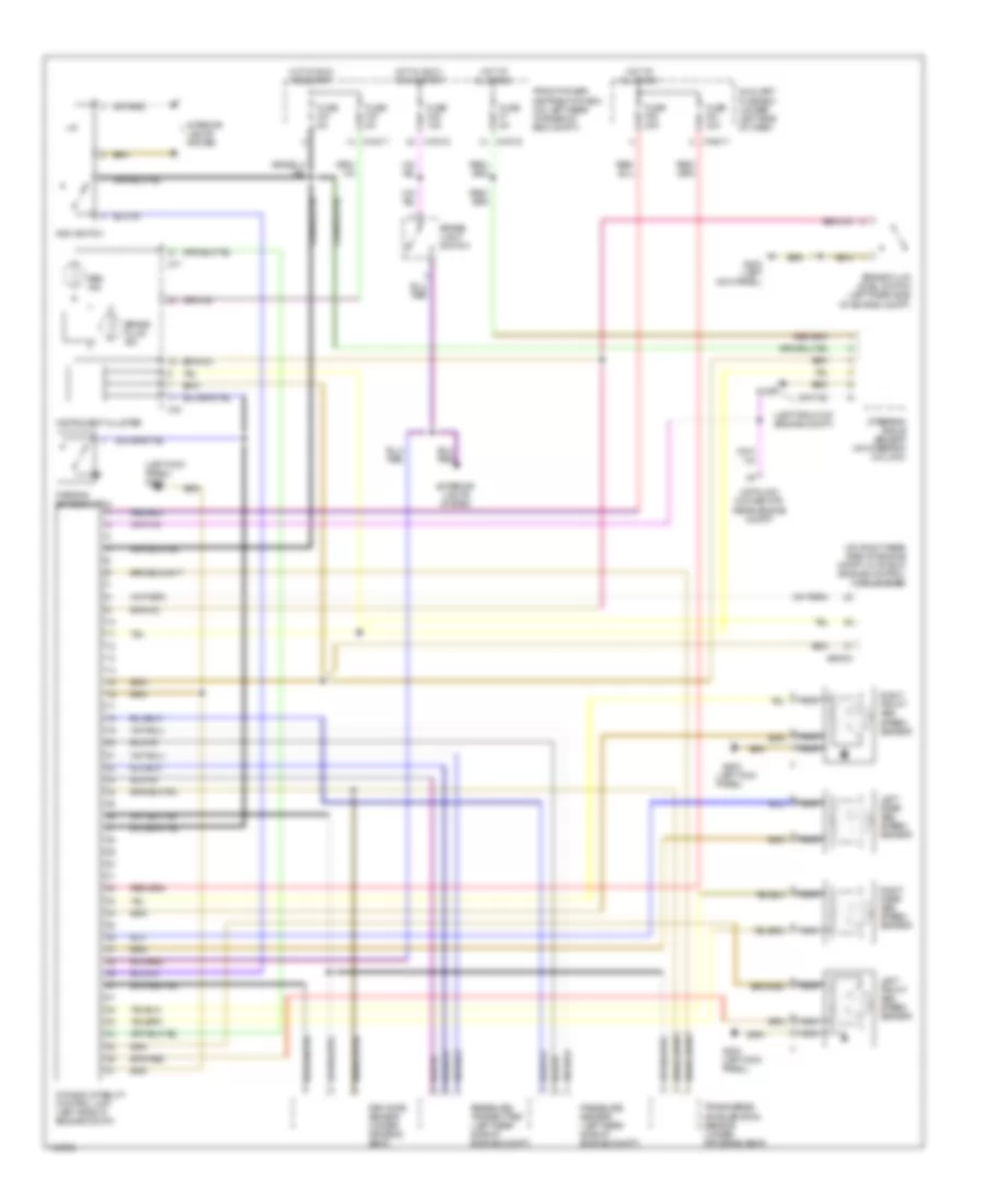
Anti-lock Brakes Wiring Diagram, with DSC Early Production for BMW M Coupe 2001

List of elements for Anti-lock Brakes Wiring Diagram, with DSC Early Production for BMW M Coupe 2001:
- (left front of engine compt)
- (left kick panel) g200
- (on right rear side of engine compt, in "e" box) engine control module (dme)
- Abs ind
- Auxiliary fuse box (under left side of dash)
- Brake fluid ind
- Brake fluid level switch (left rear side of engine compt)
- Brake light switch
- Data link connector (rear engine compt)
- Dsc switch
- Dynamic stability control unit (left side of engine compt)
- Exterior lights system
- Front power distribution box (on left rear corner of eng compt)
- Fuse f21 5a
- Fuse f27 5a
- Fuse f46 15a
- Fuse f51 30a
- Fuse f52 30a
- Fuse f53 30a
- Fuse f7 5a
- G100
- G100 (left front of engine compt)
- G200 (left kick panel)
- Hot at all times
- Hot in accy, run & start
- Hot in run and start
- Instrument cluster
- Interior lights system
- Left front abs speed sensor
- Left rear abs speed sensor
- Nca
- Parking brake switch
- Precharge pump (left rear side of engine compt)
- Pressure sensor (left rear side of engine compt)
- Pressure transmitter (left rear side of engine compt)
- Right front abs speed sensor
- Right rear abs speed sensor
- Rpm rate sensor (under driver's seat)
- Steering angle sensor (on steering column)
- Transverse acceleration sensor (under drivers's seat)
- X10015
- X10017
- X10018
- X16
- X17
- X19017
- X60004
Anti-lock Brakes Wiring Diagram, with DSC Late Production for BMW M Coupe 2001
List of elements for Anti-lock Brakes Wiring Diagram, with DSC Late Production for BMW M Coupe 2001:
- (left front of engine compt)
- (left kick panel)
- (left kick panel) g200
- (on right rear side of engine compt, in "e" box) engine control module (dme)
- Abs ind
- Auxiliary fuse box (under left side of dash)
- Brake fluid ind
- Brake fluid level switch (left rear side of engine compt)
- Brake light switch
- Data link connector (rear engine compt)
- Dsc switch
- Dynamic stability control unit (left side of engine compt)
- Exterior lights system
- Front power distribution box (on left rear corner of eng compt)
- Fuse f21 5a
- Fuse f27 5a
- Fuse f46 15a
- Fuse f51 30a
- Fuse f52 30a
- Fuse f7 5a
- G100
- G200
- G200 (left kick panel)
- Hot at all times
- Hot in accy, run & start
- Hot in run and start
- Instrument cluster
- Interior lights system
- Left front abs speed sensor
- Left rear abs speed sensor
- Nca
- Parking brake switch
- Pressure sensor (left rear side of engine compt)
- Pressure transmitter (left rear side of engine compt)
- Right front abs speed sensor
- Right rear abs speed sensor
- Rpm rate sensor (under driver's seat)
- Steering angle sensor (on steering column)
- Transverse acceleration sensor (under drivers's seat)
- X10015
- X10017
- X10018
- X16
- X17
- X19017
- X60004
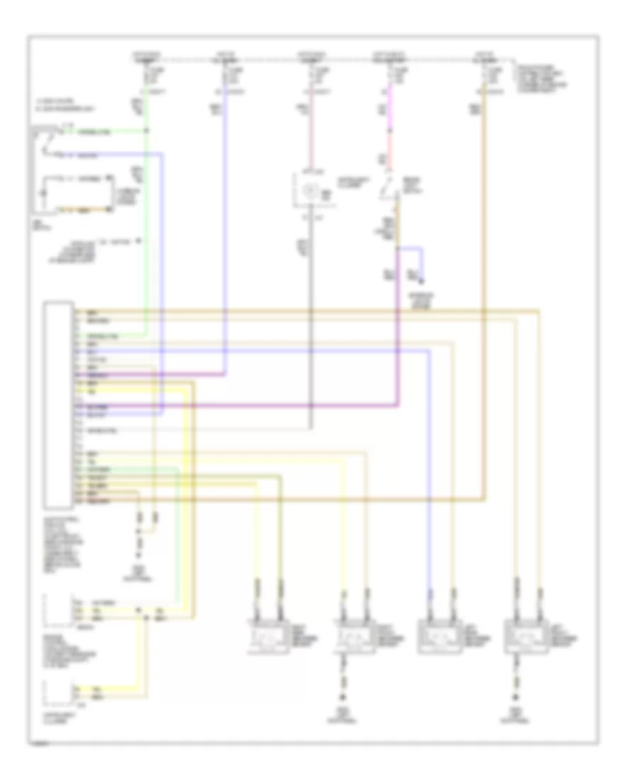
Anti-lock Brakes Wiring Diagram, with Slip Control for BMW M Coupe 2001
List of elements for Anti-lock Brakes Wiring Diagram, with Slip Control for BMW M Coupe 2001:
- 2000 coupe a
- 2000 roadster, 2001 b
- Abs ind
- Asc switch
- Brake light switch
- Data link connector (on rear side of engine compt)
- Engine control module (dme) (on right rear side of engine compt, in "e" box)
- Exterior lights system
- Front power distribution box (on left rear corner of engine compartment)
- Fuse f10 30a
- Fuse f21 5a
- Fuse f27 5a
- Fuse f38 30a
- Fuse f46 15a
- G200 (left kick panel)
- Hot at all times
- Hot in accy, run & start
- Hot in run & start
- Instrument cluster
- Interior lights system
- Left front abs speed sensor
- Left rear abs speed sensor
- Nca
- Right front abs speed sensor
- Right rear abs speed sensor
- Slip control module (2.5l, 2.8l : in left front side of engine compt, 3.2l : under right side of dash, behind glove box)
- X10015
- X10017
- X10018
- X16
- X17
- X60004