ANTI-LOCK BRAKES
Anti-lock Brakes Wiring Diagram for BMW X5 xDrive50i 2014
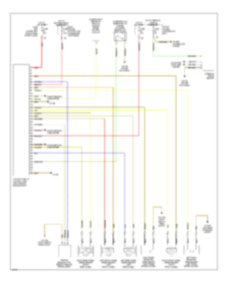
List of elements for Anti-lock Brakes Wiring Diagram for BMW X5 xDrive50i 2014:
- (in brake fluid reservoir, on master cylinder) brake fluid level switch
- (under front center of vehicle) parking brake control module
- Body domain controller (passenger kick panel)
- Computer data lines system
- Dynamic stability control (dsc) (right side of engine compt)
- Front power distribution box
- Fuse 30a
- Fuse 50a
- Fuse 5a
- Fuse 7.5a
- Fuse box (under left side of rear compt floor)
- Hot at all times
- Hot w/ bi-stable relay energized
- Hot w/ terminal 15 relay energized
- Left front brake pad wear sensor (left front brake caliper)
- Left front wheel speed sensor (left front wheel)
- Left rear wheel speed sensor (left rear wheel)
- Nca
- Parking brake button (base of parking brake lever)
- Power distribution system
- Red
- Right front wheel speed sensor (right front wheel)
- Right rear brake pad wear sensor (right rear brake caliper)
- Right rear wheel speed sensor (right rear wheel)
- Steering angle sensor
- Z10 14b (right side of rear compt)
- Z10 20b (left rear of engine compt)
- Z10 3b
- Z10 7b (driver kick panel)
 English