ANTI-LOCK BRAKES
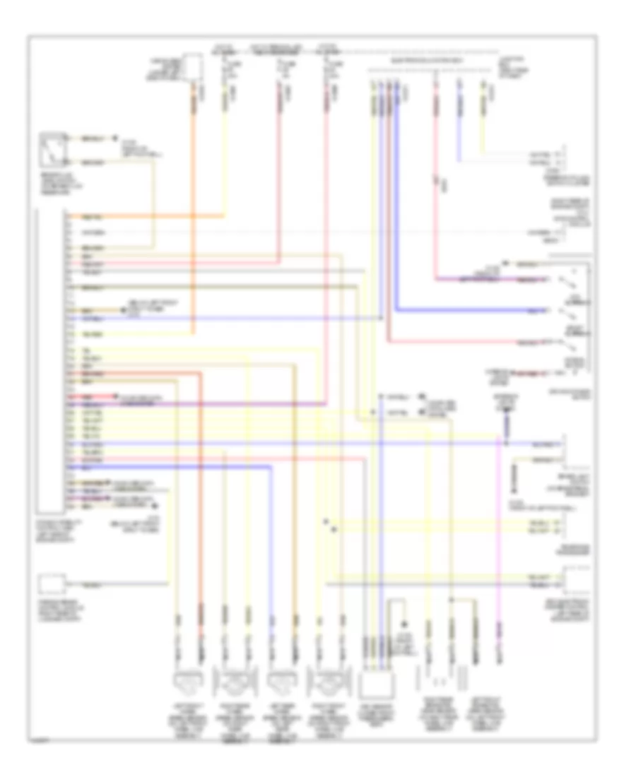
Anti-lock Brakes Wiring Diagram for BMW Z4 sDrive28i 2014
List of elements for Anti-lock Brakes Wiring Diagram for BMW Z4 sDrive28i 2014:
- (below left front strut tower) x170
- (right rear of engine compt) (3.0l) dme control module
- Brake fluid level switch (on brake fluid reservoir)
- Brake light switch (on brake pedal bracket)
- Car access system (under left side of dash)
- Computer data lines system
- Driving dynamic switch
- Dsc sensor (under front passenger's seat)
- Dtc button
- Dynamic stability control (dsc) (left side of engine compt)
- Edc electronic damper control (left rear of engine compt)
- Electronics junction box
- Exterior lights system
- Fuse 30a
- Fuse 40a
- Fuse 5a
- Hot at all times
- Hot w/ terminal 30g relay energized
- Interior lights system
- Junction box (right side of dash)
- Left front brake pad wear sensor (on left front wheel hub assembly)
- Left front wheel speed sensor (on left front wheel hub assembly)
- Left rear wheel speed sensor (on left rear wheel hub assembly)
- Nca
- Normal button
- Parking brake control module (right rear of luggage compt)
- Red
- Right front wheel speed sensor (on right front wheel hub assembly)
- Right rear brake pad wear sensor (on right rear wheel hub assembly)
- Right rear wheel speed sensor (on right rear wheel hub assembly)
- Sport button
- Steering column switch cluster
- Telephone transceiver
- X11001
- X11007
- X11008
- X1108 (front of left footwell)
- X13376
- X14271
- X14272
- X170 (below left front strut tower)
- X1880
- X60001
- X9331
 English