ANTI-LOCK BRAKES
Anti-lock Brakes Wiring Diagram (1 of 2) for Buick Allure CX 2009

List of elements for Anti-lock Brakes Wiring Diagram (1 of 2) for Buick Allure CX 2009:
- (5.3l) j125
- (5.3l: left side of engine) (3.8l: left rear of engine)
- (i/p wiring harness, 14 cm from pass- through to brake fluid level switch)
- (off-engine wiring harness, 6 cm from breakout to brake fluid pressure sensor)
- (right front wheel hub assembly) (w/ active brake control) right front wheel speed sensor (wss)
- (right rear wheel hub assembly) (w/ active brake control) right rear wheel speed sensor (wss)
- 5-volt ref
- 5.3l
- A11
- Abs fuse 10a
- Abs fuse 23 10a
- Abs mtr fuse 31 40a
- Abs mtr fuse 40a
- Abs sol fuse 19 25a
- Abs sol fuse 25a
- Actuator ctrl
- Batt pos
- Batt pos volt
- Brake fluid pressure sensor (w/ active brake control)
- Brake pressure modulator valve (bpmv)
- Class 2 serial data
- Computer data lines system
- Delivered torque sig
- Electronic brake control module (ebcm) (integral to brake pressure modulator valve)
- Engine spd sig
- Engine spd sig hi spd serial data (-)
- Except 5.3l
- G115
- Ground
- Hi spd serial data (+)
- Hi spd serial data (-)
- Hot at all times
- Hot w/ ign 1 relay energized
- Hot w/ ignition main pcb relay energized
- Ign volt
- J107
- J216
- Lateral accelerometer sig
- Left front wheel speed sensor (wss) (w/ active brake control) (left front wheel hub assembly)
- Left rear wheel speed sensor (wss) (w/ active brake control) (left rear wheel hub assembly)
- Low ref
- Nca
- Pnk
- Red
- Requested torque sig
- Sens sig
- Steering angle sensor (w/ active brake control) (base of steering column)
- Stop lamp sw sig
- Tan
- Underhood fuse block (right front strut tower)
- Variable effort steering actuator
- W/ active brake control
- W/o active brake control
- Yaw rate sens sig
- Yaw rate sens test ctrl
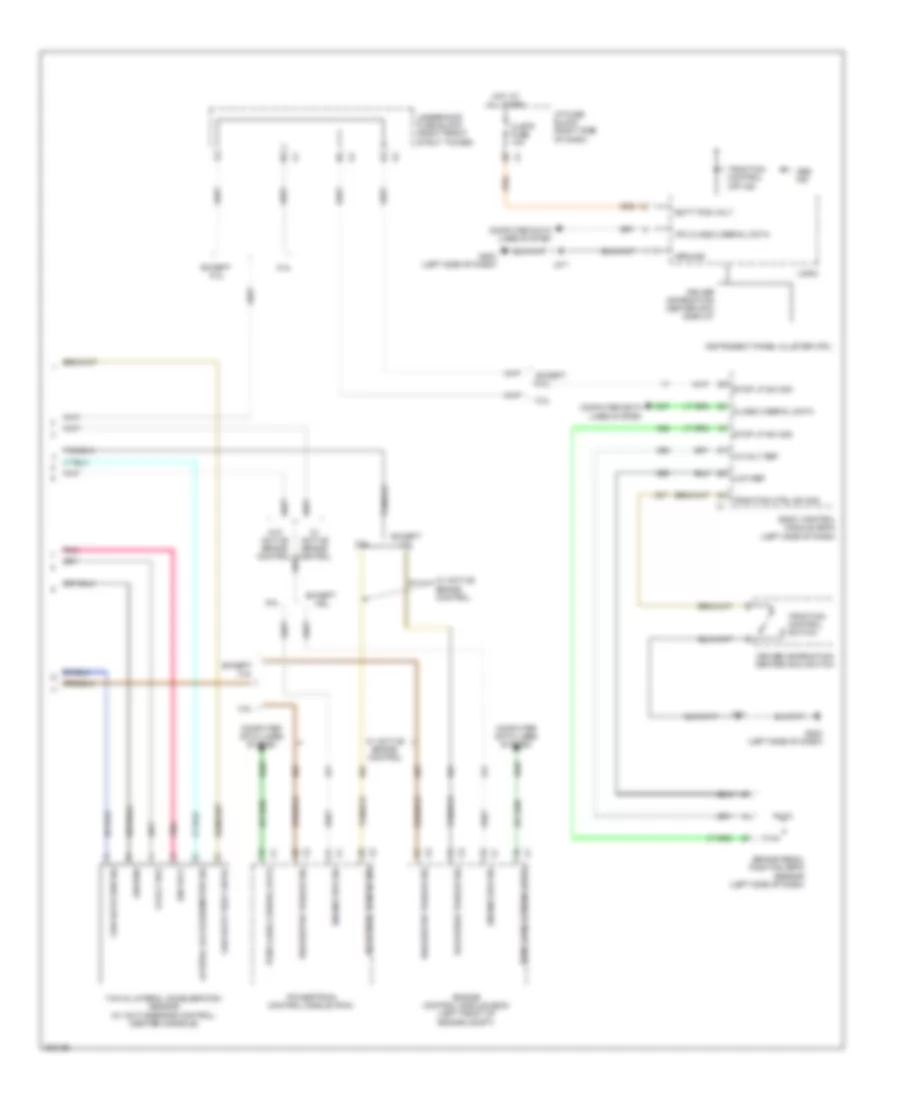
Anti-lock Brakes Wiring Diagram (2 of 2) for Buick Allure CX 2009
List of elements for Anti-lock Brakes Wiring Diagram (2 of 2) for Buick Allure CX 2009:
- 10-volt ref
- 3.8l
- 5-volt ref
- 5.3l
- Abs ind
- Batt pos volt
- Body control module (bcm) (left side of dash)
- Brake pedal position (bpp) sensor (left side of dash)
- Class 2 serial data
- Clstr fuse 10a
- Computer data lines system
- Delivered torque sig
- Driver information center (dic) display
- Driver information center (dic) switch
- Ecm class 2 serial data
- Engine control module (ecm) (left front of engine compt)
- Engine spd sig
- Except 3.8l
- Except 5.3l
- G202 (left side of dash)
- Ground
- Hot at all times
- I/p fuse block (right side of dash)
- Ign volt
- Instrument panel cluster (ipc)
- Ipc class 2 serial data
- J211
- Lateral accelerometer sig
- Logic
- Low ref
- Pcm class 2 serial data
- Pnk
- Powertrain control module (pcm)
- Requested torque sig
- Stop lp sw sig
- Traction control off ind
- Traction control switch
- Traction ctrl sw sig
- Underhood fuse block (right front strut tower)
- W/ active brake control
- W/o active brake control
- Yaw & lateral acceleration sensor (w/ active brake control) (center console)
- Yaw rate sen sig
- Yaw rate test cntrl