ANTI-LOCK BRAKES
Anti-lock Brake Wiring Diagrams (1 of 2) for Buick Century Custom 1995

List of elements for Anti-lock Brake Wiring Diagrams (1 of 2) for Buick Century Custom 1995:
- 15a
- Abs hydraulic modulator (left shock tower)
- Abs ind ctrl
- Battery
- Brake ind ctrl
- Brake input
- C 1995 vftc
- Data line
- E10
- E11
- Ecbm independent lamp driver module (left side of i/p, left
- Electronic brake control module (ebcm) (behind right front of i/p, above powertrain control module)
- Electronic brake control relay (behind right front shock tower, on firewall)
- F10
- F11
- F12
- Fan/alt fuse 10a
- Fuse block
- Fuse link g (14 ga-rust) (front of engine compt, near battery)
- G108 (left front of engine compt, on radiator support)
- G206 (right shroud, near center access hole)
- Gages fuse 10a
- Ground
- Hot at all times
- Hot in accy or run
- Hot in run, bulb test or start
- Ignition/run input
- Left front abs solenoid
- Left front motor
- Left front sol ctrl
- Left front wheel speed sensor
- Left rear wheel speed sensor
- Low traction ind ctrl
- Multi-function alarm in-line fuse (behind right side of i/p, taped on harness near fuse block)
- Of steering column)
- Pnk
- Rear motor
- Red
- Relay contrl
- Right front abs solenoid
- Right front motor
- Right front sol ctrl
- Right front wheel speed sensor
- Right rear wheel speed sensor
- Solid state
- Stop lamp brake switch (on brake pedal support)
- Stop/haz fuse 20a
- Switched ignition
- Tan
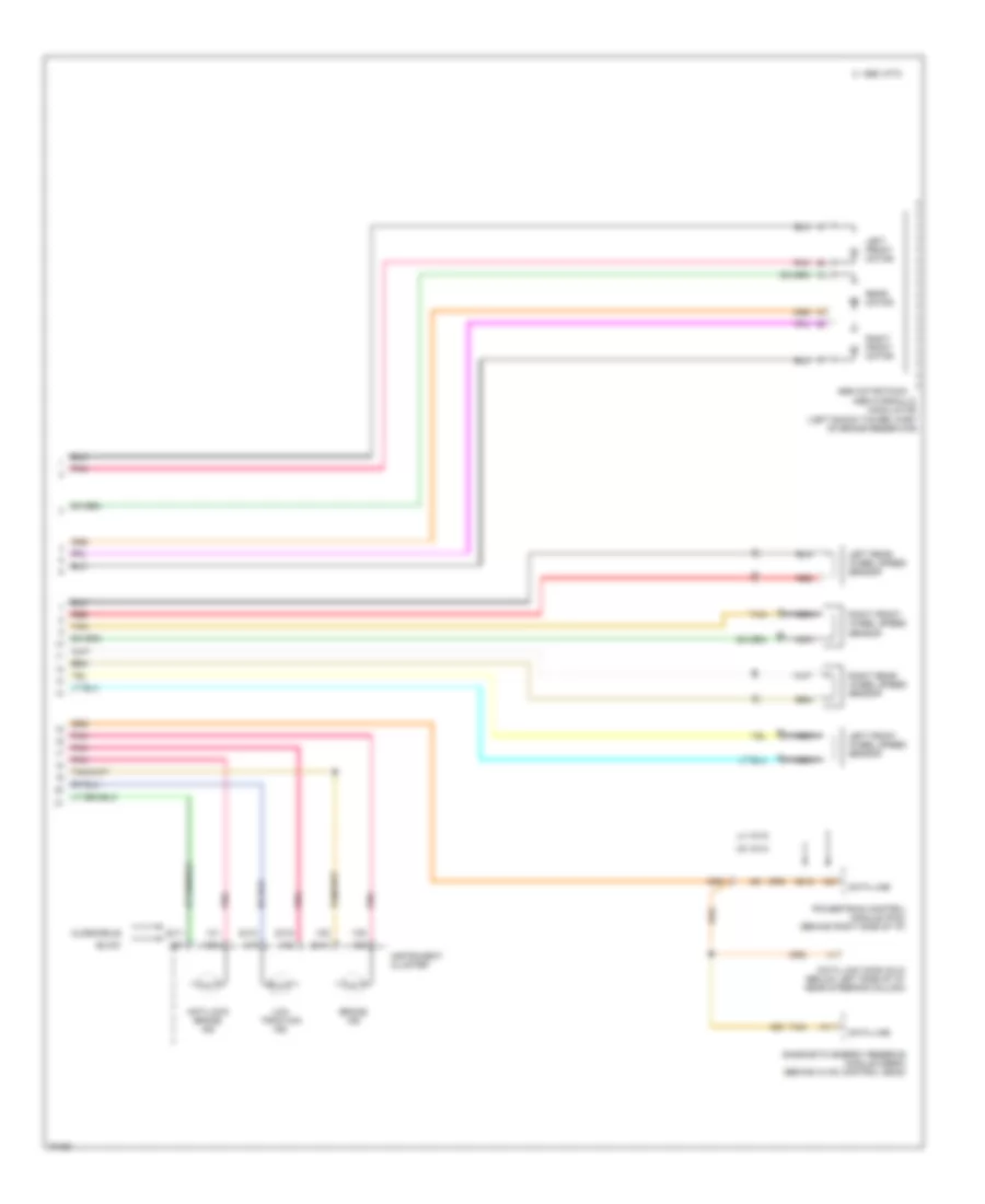
Anti-lock Brake Wiring Diagrams (2 of 2) for Buick Century Custom 1995
List of elements for Anti-lock Brake Wiring Diagrams (2 of 2) for Buick Century Custom 1995:
- 12c8
- 1c1
- 1c2
- 1c5
- 1c6
- 1c7
- 1c9
- 2c10
- 2c11
- 2c14
- 2c16
- 2c7
- 3d12
- A11
- Abs motor pack
- Anti-lock brake ind
- Asb hydraulic modulator (left shock tower, part of brake reservoir)
- Brake ind
- Buick
- C 1995 vftc
- Data line
- Data link conn (dlc) (below left side of i/p, near steering column)
- Diagnostic energy reserve module (derm) (behind hvac control head)
- Instrument cluster
- L4 vin d
- Left front motor
- Left front wheel speed sensor
- Left rear wheel speed sensor
- Low traction ind
- Nca
- Oldsmobile
- Pnk
- Powertrain control module (pcm) (behind right side of i/p)
- Rear motor
- Red
- Right front motor
- Right front wheel speed sensor
- Right rear wheel speed sensor
- Tan
- V6 vin m