ANTI-LOCK BRAKES
Anti-lock Brakes Wiring Diagram (1 of 2) for Buick Lucerne CXL 2006

List of elements for Anti-lock Brakes Wiring Diagram (1 of 2) for Buick Lucerne CXL 2006:
- (base of steering column) (w/ active brake control) steering angle sensor
- (left front corner of engine compt) electronic brake control module (ebcm)
- (on floor pan, left of center console) (w/ active brake control) yaw & lateral acceleration sensor
- 5v ref
- Abs 1 fuse 50a
- Abs 2 fuse 60a
- Abs ind
- Batt pos volt
- Brake pressure modulator valve (bpmv)
- Computer data lines system
- Electronic power steering system
- Erometer sig long accel-
- G114 (lower left rear of engine)
- Gmlan (bcm)
- Gmlan (ebcm)
- Ground
- High effort ctrl
- Hot at all times
- Hot w/ run/crnk relay energized
- Hvac fuse 10a
- Ign
- Ign 1 volt
- Instrument panel cluster (ipc)
- Lateral accel- erometer sig
- Lateral accelerometer sig
- Left front inlet
- Left front isolation
- Left front outlet
- Left front prime
- Left rear inlet
- Left rear outlet
- Logic
- Long accelerometer signal
- Low effort ctrl
- Low ref
- Low reference
- Motor ctrl
- Pnk
- Position signal a
- Position signal b
- Radio
- Red
- Right front inlet
- Right front isolation
- Right front outlet
- Right front prime
- Right rear inlet
- Right rear outlet
- Sensor signal
- Serial data
- Serial data (+)
- Serial data (-)
- Serial data wake up
- Sol valve ctrl
- Solenoid valves
- Tan
- Traction ind
- Underhood fuse block (on right front of engine compt, forward of strut tower)
- Vehicle speed signal
- Vss
- Yaw rate diagnostic
- Yaw rate sensor sig
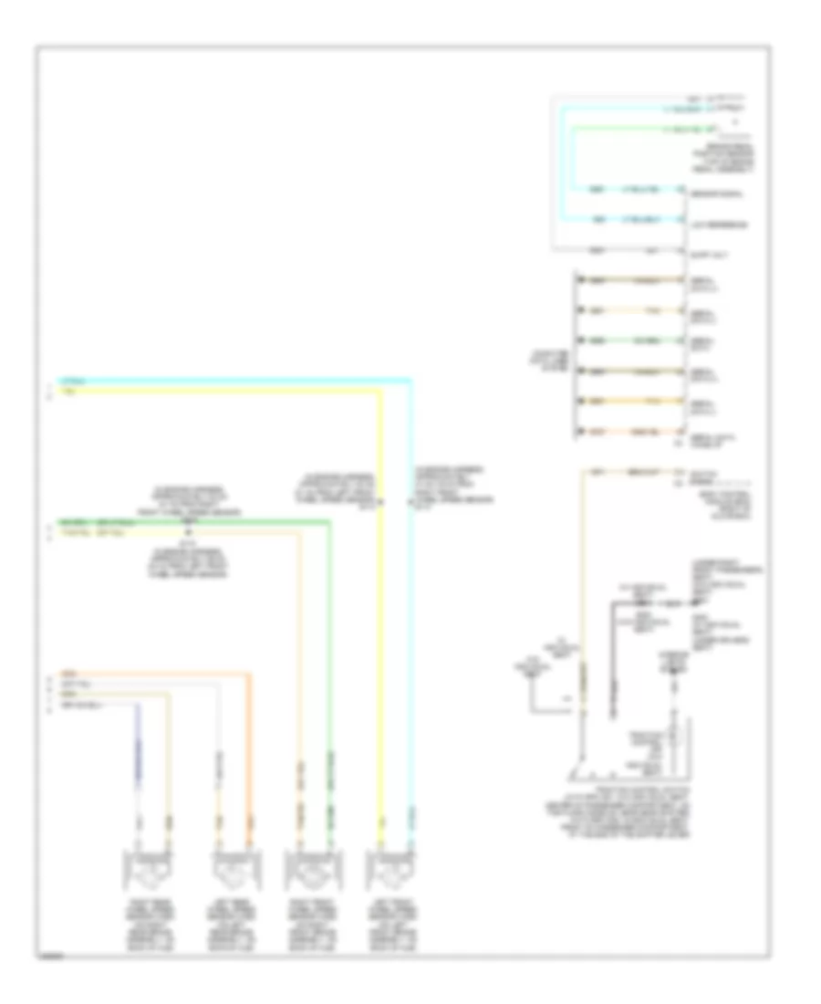
Anti-lock Brakes Wiring Diagram (2 of 2) for Buick Lucerne CXL 2006
List of elements for Anti-lock Brakes Wiring Diagram (2 of 2) for Buick Lucerne CXL 2006:
- (in engine harness, approximately 47 cm (19 in) from right front wheel speed sensor) s114
- (in engine harness, approximately 53 cm (21 in) from left front wheel speed sensor) s113
- (in engine harness, approximately 53 cm (21 in) from right front wheel speed sensor) s116
- (under right front passenger's seat) (w/o individual seat) g304
- (w/ individual seat) s204
- Body control module (bcm) (right of glove box)
- Brake pedal position sensor (top of brake pedal assembly)
- Computer data lines system
- G300 (w/ individual seat) (under driver's seat)
- Interior lights system
- Left front wheel speed sensor (wss) (on left front brake assembly, on back of hub)
- Left rear wheel speed sensor (wss) (on left rear brake assembly, on back of hub)
- Low reference
- Right front wheel speed sensor (wss) (on right front brake assembly, on back of hub)
- Right rear wheel speed sensor (wss) (on right rear brake assembly, on back of hub)
- S115 (in engine harness, approximately 59 cm (24 in) from left front wheel speed sensor)
- S383 (w/o individual seat)
- Sensor signal
- Serial data
- Serial data (+)
- Serial data (-)
- Serial data wake up
- Supp volt
- Switch signal
- Tan
- Traction control off (w/o individual seat)
- Traction control switch (with rpo a51: w/o individual seat: center of passenger compartment, on the floor console, near gear shifter) (with rpo an3: w/individual seat: front of passenger compartment, at the end of the shifter lever)
- W/ individual seat
- W/o individual seat