ANTI-LOCK BRAKES
Anti-lock Brakes Wiring Diagram, with Traction Control for Buick Rainier 2004

List of elements for Anti-lock Brakes Wiring Diagram, with Traction Control for Buick Rainier 2004:
- (4.2l)
- (5.3l)
- (not used)
- (on bottom left side of dash) data link connector (dlc)
- 4.2l
- 5.3l
- A10
- Abs fuse 33 60a
- Abs pump
- Anti-lock indicator
- B10
- Body control module (bcm) (beneath left rear seat, on rear fuse block)
- Brake fluid level switch (on brake master cylinder fluid reservoir)
- Brake fluid lvl sig
- Brake fuse 51 10a
- Brake indicator
- C11
- Cruise control system
- Delivered torque sig
- Delivered torque signal
- Dimming
- Electronic brake control module (ebcm) (on inner left frame rail, beside transmission)
- G107 (on lower left side of engine)
- G201
- G304 (on outside of left frame rail, near electronic brake control module)
- Grd
- Hot at all times
- Hot in run
- Hot in run or start
- Hvac 1 fuse 39 10a
- Ign 1
- Ign e fuse 22 10a
- Ignition 3
- Instrument panel cluster
- Interior lights system
- Inverting driver module (in center console)
- Ipc/dic fuse 24 10a
- Left front wheel speed sensor
- Lf whl spd sens ref
- Lf whl spd sens sig
- Off ind ctrl
- Passive ind ctrl
- Pnk
- Powertrain control module (pcm) (4.2l: on upper left side of engine, 5.3l: near lower left front of engine)
- Rear fuse block (below left rear seat)
- Red
- Requested torque sig
- Requested torque signal
- Resistor
- Rf whl spd sens ref
- Rf whl spd sens sig
- Right front wheel speed sensor
- S239
- S300
- S307
- Serial data
- Sp201 (lower right front of lower console)
- Sp205 (behind left of dash, near headlamp switch connector)
- Stop lamp switch (above brake pedal, on bracket)
- Tan
- Tcc brake switch sig
- Trac active telltale
- Trac disable telltale
- Traction control switch
- Traction disable sw
- Underhood fuse block (left side of engine compt)
- Vehicle speed signal
- Vss
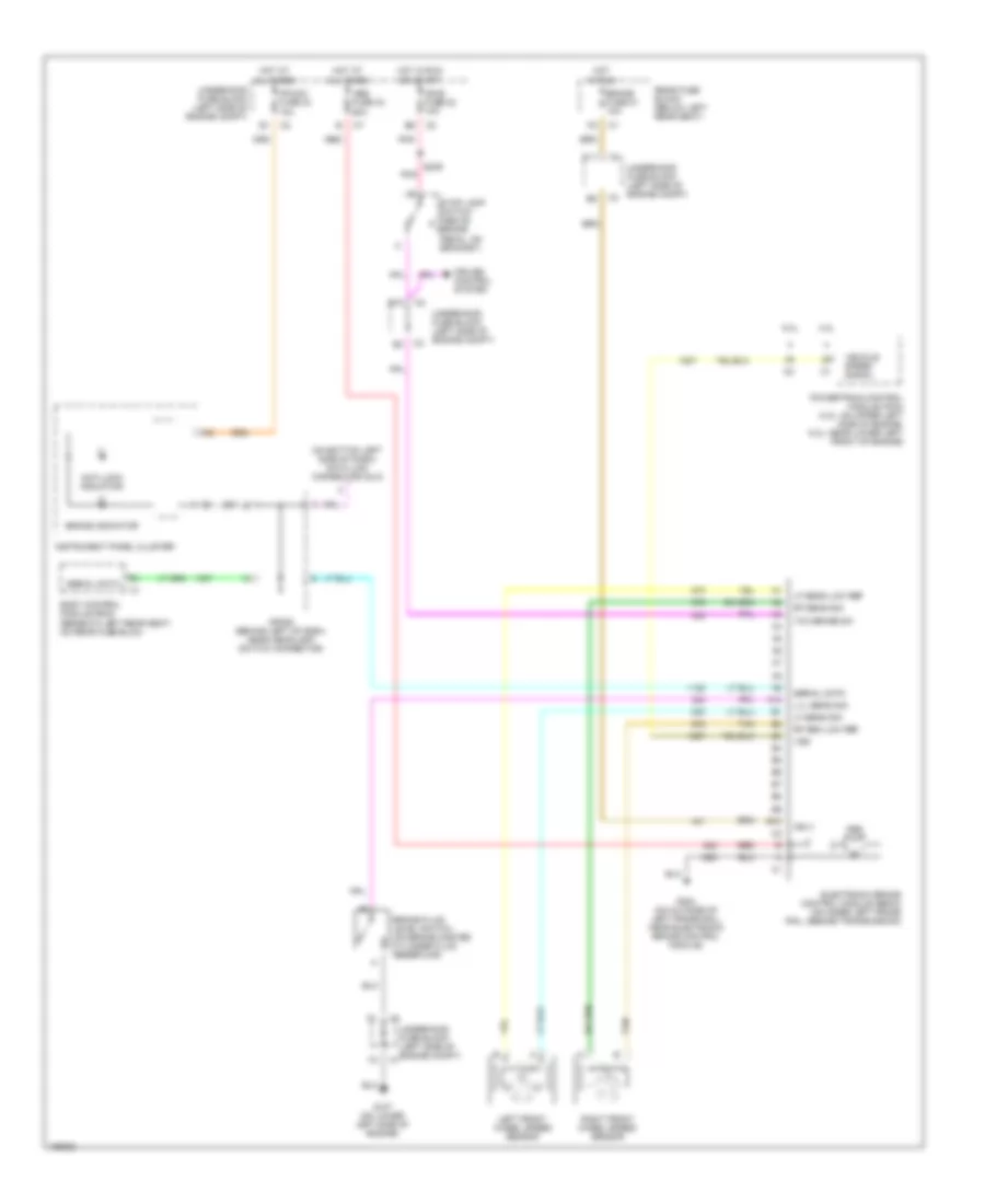
Anti-lock Brakes Wiring Diagram, without Traction Control for Buick Rainier 2004
List of elements for Anti-lock Brakes Wiring Diagram, without Traction Control for Buick Rainier 2004:
- (on bottom left side of dash) data link connector (dlc)
- 4.2l
- 5.3l
- A10
- Abs fuse 33 60a
- Abs pump
- Anti-lock indicator
- B10
- Body control module (bcm) (beneath left rear seat, on rear fuse blck)
- Brake fluid level switch (on brake master cylinder fluid reservoir)
- Brake fuse 51 10a
- Brake indicator
- C11
- Cruise control system
- Electronic brake control module (ebcm) (on inner left frame rail, beside transmission)
- G107 (on lower left side of engine)
- G304 (on outside of left frame rail, near electronic brake control module)
- Hot at all times
- Hot in run
- Hot in run or start
- Ign 3
- Ign e fuse 22 10a
- Instrument panel cluster
- Ipc/dic fuse 24 10a
- Left front wheel speed sensor
- Lf sens low ref
- Lf sens sig
- Lvl sens sig
- Pnk
- Powertrain control module (pcm) (4.2l: on upper left side of engine, 5.3l: near lower left front of engine)
- Rear fuse block (below left rear seat)
- Red
- Rf sen low ref
- Rf sens sig
- Right front wheel speed sensor
- S239
- Serial data
- Sp205 (behind left of dash, near headlamp switch connector)
- Stop lamp switch (above brake pedal, on bracket)
- Tan
- Tcc brake sw
- Underhood fuse block (left side of engine compt)
- Vehicle speed signal
- Vss