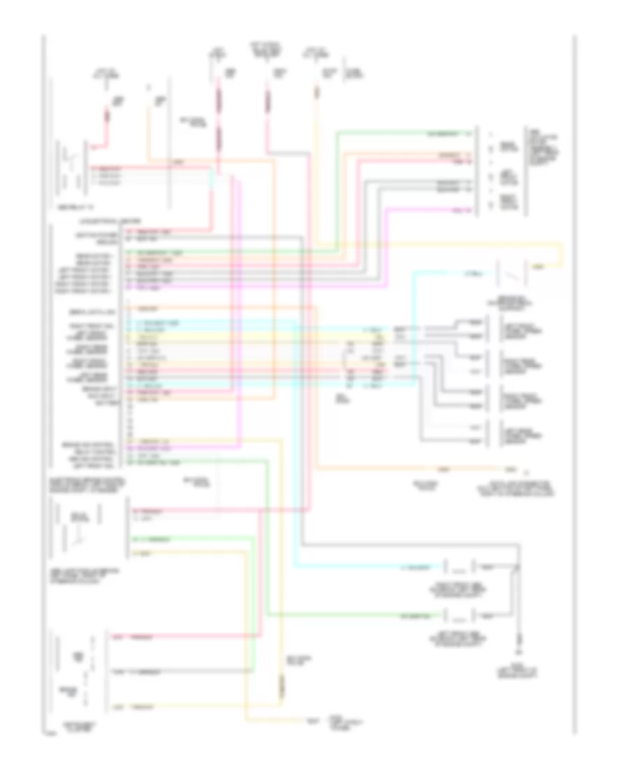
ANTI-LOCK BRAKES
Anti-lock Brake Wiring Diagrams for Buick Regal Limited 1994
List of elements for Anti-lock Brake Wiring Diagrams for Buick Regal Limited 1994:
- (dlc) (bottom of inst panel,
- (left front of
- (left rear
- (left strut
- (on brake pedal
- 10a
- 15a
- 60a
- Abs
- Abs ind control
- Abs lamp module (behind
- Abs relay "a"
- Actuator
- All times
- Assembly
- B/h
- B/h conn
- Battery
- Block
- Brake
- Brake ind control
- Brake input
- Brake sw
- Bulb test
- C16
- Cluster
- Compt)
- Conn
- D10
- D16
- Data link connector
- Electronic brake control
- Engine compt)
- Engine compt, in fender)
- Front
- Fuse
- G102
- G108
- Ground
- Hot
- Hot at
- Hot in run,
- Ignition power
- In run
- Ind
- Indic
- Inst panel, right of
- Instrument
- Left
- Left front
- Left front abs
- Left front motor +
- Left front motor /
- Left front sol
- Left rear
- Ls electrical center
- Module (ebcm) (left side of
- Motor
- Nca
- Of engine
- Of engine compt)
- Or start
- Pin a6
- Pin c2
- Pin g3
- Pin g6
- Pnk
- Pnk 1281
- Rear
- Rear motor +
- Rear motor /
- Red
- Red 885
- Relay control
- Right
- Right front
- Right front abs
- Right front motor +
- Right front motor /
- Right front sol
- Right of steering column)
- Right rear
- Run input
- Sensor
- Serial data link
- Solenoid (left rear
- Solid
- State
- Steering column)
- Stop
- Support)
- Tan
- Tan 833
- Tower)
- Wheel sensor
- Wheel speed
 English