ANTI-LOCK BRAKES
Anti-lock Brake Wiring Diagrams for Buick Regal LS 1997
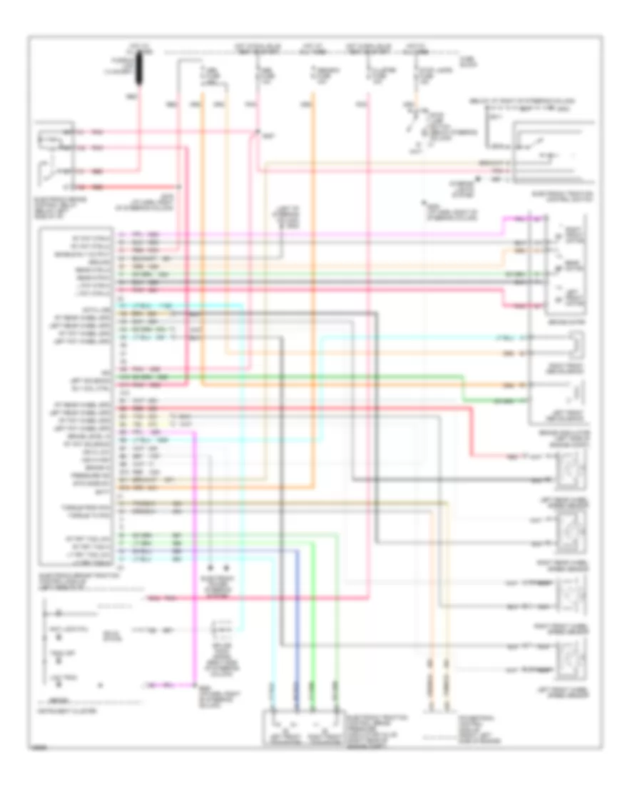
List of elements for Anti-lock Brake Wiring Diagrams for Buick Regal LS 1997:
- (below i/p, right of steering column)
- (left of steering column) g202
- A10
- A11
- A12
- Abs fuse 10a
- Abs-bcm fuse 10a
- Anti lock fail
- B10
- B11
- B12
- Batt
- Brake
- Brake in
- Brake level in
- Brake modulator (left side of engine compt)
- Brake motor
- C1 stop lamp switch (below steering column)
- Cluster fuse 10a
- Data line
- Electronic brake control relay (below left side of i/p)
- Electronic brake traction control module (left side of i/p)
- Electronic power steering system
- Electronic traction control brake pressure modulator valve (right rear of engine compt)
- Electronic traction control switch
- Enable rly output
- Ets mode sw
- Fuse block
- G202
- Ground
- Hot at all times
- Hot in run, bulb test or start
- Ign
- Instrument cluster
- Interior lights system
- L fnt mtr-hi
- L fnt mtr-lo
- Left fnt wheel spd
- Left front abs solenoid
- Left front motor
- Left front tcs motor
- Left front wheel speed sensor
- Left rear wheel spd
- Left rear wheel speed sensor
- Left solenoid
- Low trac
- Lt frt tcs hi
- Lt frt tcs low
- Msva high
- Msva low
- Nca
- Pnk
- Powertrain control module (front left side of engine)
- Pressure ind
- Rear motor
- Rear mtr-hi
- Rear mtr-lo
- Red
- Right front abs solenoid
- Right front motor
- Right front tcs motor
- Right front wheel speed sensor
- Right rear wheel speed sensor
- Rly coil ctrl
- Rt fnt mtr-hi
- Rt fnt mtr-lo
- Rt fnt solenoid
- Rt fnt wheel spd
- Rt frt tcs hi
- Rt frt tcs low
- Rt rear wheel spd
- S205 (i/p harn, right of steering column)
- S211
- S279 (i/p harn, right of steering column)
- S286 (i/p harn, right of steering column)
- S287
- Solid state
- Splice pack (sp205) (right side of steering column)
- Stop lamps fuse 15a
- Tan
- Torque from pcm
- Torque to pcm
- Trac off
 English