ANTI-LOCK BRAKES
Anti-lock Brake Wiring Diagrams for Buick Regal LS 2002
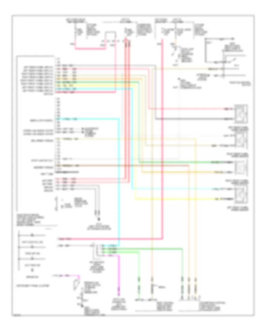
List of elements for Anti-lock Brake Wiring Diagrams for Buick Regal LS 2002:
- A10
- A11
- Abs fuse 1 60a
- Abs fuse 10a
- Anti-lock fail ind
- B10
- B11
- B12
- Battery
- Body control module (bcm) (behind left side of dash)
- Brake fluid level switch (in brake fluid reservoir)
- Brake ind
- Brake pressure modulator valve
- C10
- C11
- Cluster fuse 10a
- Data link connector (dlc) (under left side of dash)
- Delivered torque
- Desired torque
- Electronic brake control module (ebcm) (at left side of engine compt, near strut tower)
- Electronic power steering system
- G113 (left of starter, on transaxle stud)
- G203 (below dash, right side of steering column)
- Ground
- Hot at all times
- Hot in run or start
- Hot in run, bulb test or start
- I/p fuse block (behind right side of dash)
- Ignition
- Instrument panel cluster
- Interior lights system
- Left front wheel spd (hi)
- Left front wheel spd (lo)
- Left front wheel speed sensor
- Left rear wheel spd (hi)
- Left rear wheel spd (lo)
- Left rear wheel speed sensor
- Low trac ind
- Nca
- Pnk
- Powertrain control module (pcm) (left front side of engine compt)
- Pump motor
- Red
- Regal
- Right front wheel spd (hi)
- Right front wheel spd (lo)
- Right front wheel speed sensor
- Right rear wheel spd (hi)
- Right rear wheel spd (lo)
- Right rear wheel speed sensor
- S205 (i/p harn, right side of steering column)
- S211
- Serial data signal
- Splice pack sp205 (right side of steering column)
- Stop lamp sw out
- Stop lamp switch (on brake pedal support bracket)
- Stop lamps fuse 15a
- Strng var assist motor
- Tan
- Trac off ind
- Traction control switch
- Underhood fuse block (mounted to right strut tower)
- Vent tube
 English