ANTI-LOCK BRAKES
Anti-lock Brakes Wiring Diagram (1 of 2) for Cadillac CTS V 2010

List of elements for Anti-lock Brakes Wiring Diagram (1 of 2) for Cadillac CTS V 2010:
- (info not available)
- (left rear wheel hub assembly) left rear wheel speed sensor (wss)
- 5 volt ref
- 5v ref
- 5v ref volt
- 5v volt ref
- Abs fuse 30a
- Abs mtr fuse 50a
- Battery positive voltage
- Brake booster vaccum sensor sig
- Brk vac pump fuse (except 6.2l) 20a
- Can bus high
- Can bus high serial data
- Can bus low
- Can bus low serial data
- Computer data lines system
- Disply fuse 10a
- Ecm/tcm fuse 15a
- Electronic brake control module (ebcm) (right front corner of engine compt)
- G110 (near abs module)
- G200 (left kick panel)
- G201 (right kick panel)
- Gmlan serial data bus+
- Gmlan serial data bus-
- Gnd
- Hot at all times
- Hot w/ ign 1 relay energized
- J205
- Left front wheel speed sensor (wss) (left front wheel hub assembly)
- Lh frt wheel spd sens low ref
- Lh frt wheel spd sens sig
- Lh rr wheel spd sens low ref
- Lh rr wheel spd sens sig
- Low ref
- Nca
- Pnk
- Power distribution system
- Red
- Rh frt wheel spd sens low ref
- Rh frt wheel spd sens sig
- Rh rr wheel spd sens low ref
- Rh rr wheel spd sens sig
- Right rear wheel speed sensor (wss) (right rear wheel hub assembly)
- Serial data communication enable
- Steering wheel position sensor (top of steering column)
- Tan
- Underhood fuse block (right front of engine compt)
- Vacuum pump relay control
- Variable effort steering actr ctrl
- Variable effort steering actr sply volt
- Vehicle speed signal
- X101
- X104
- X202
- Yaw & lateral accelerometer sensor (under center console)
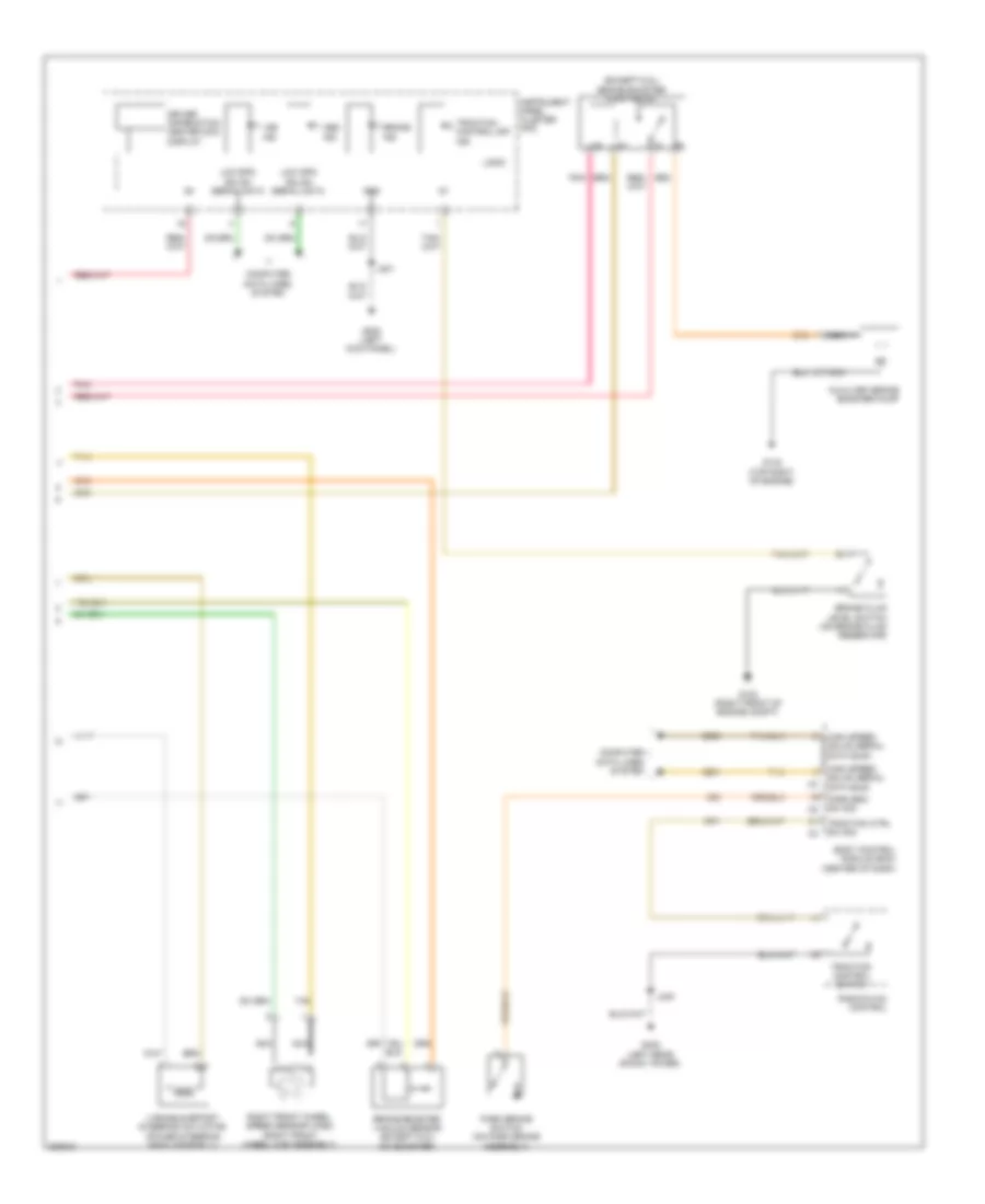
Anti-lock Brakes Wiring Diagram (2 of 2) for Cadillac CTS V 2010
List of elements for Anti-lock Brakes Wiring Diagram (2 of 2) for Cadillac CTS V 2010:
- (except 6.2l) brake booster pump relay
- Abs ind
- Auxiliary brake booster pump
- Body control module (bcm) (center of dash)
- Brake booster vacuum sensor (except 6.2l) (on booster)
- Brake fluid level switch (on brake fluid reservoir)
- Brake ind
- Computer data lines system
- Driver information center (dic) display
- G102 (right front of engine compt)
- G132 (top right of engine)
- G200 (left kick panel)
- G402 (left rear shock tower)
- Gnd
- High speed gmlan serial data bus+
- High speed gmlan serial data bus-
- Instrument panel cluster (ipc)
- J201
- J240
- Logic
- Low spd gmlan serial data
- Nca
- Park brake switch (on park brake assembly)
- Park brk sw sig
- Pnk
- Radio/hvac control
- Right front wheel speed sensor (wss) (right front wheel hub assembly)
- Tan
- Traction control off ind
- Traction control switch
- Traction ctrl sw sig
- Variable effort steering actuator (power steering rack assembly)
- Vsc ind