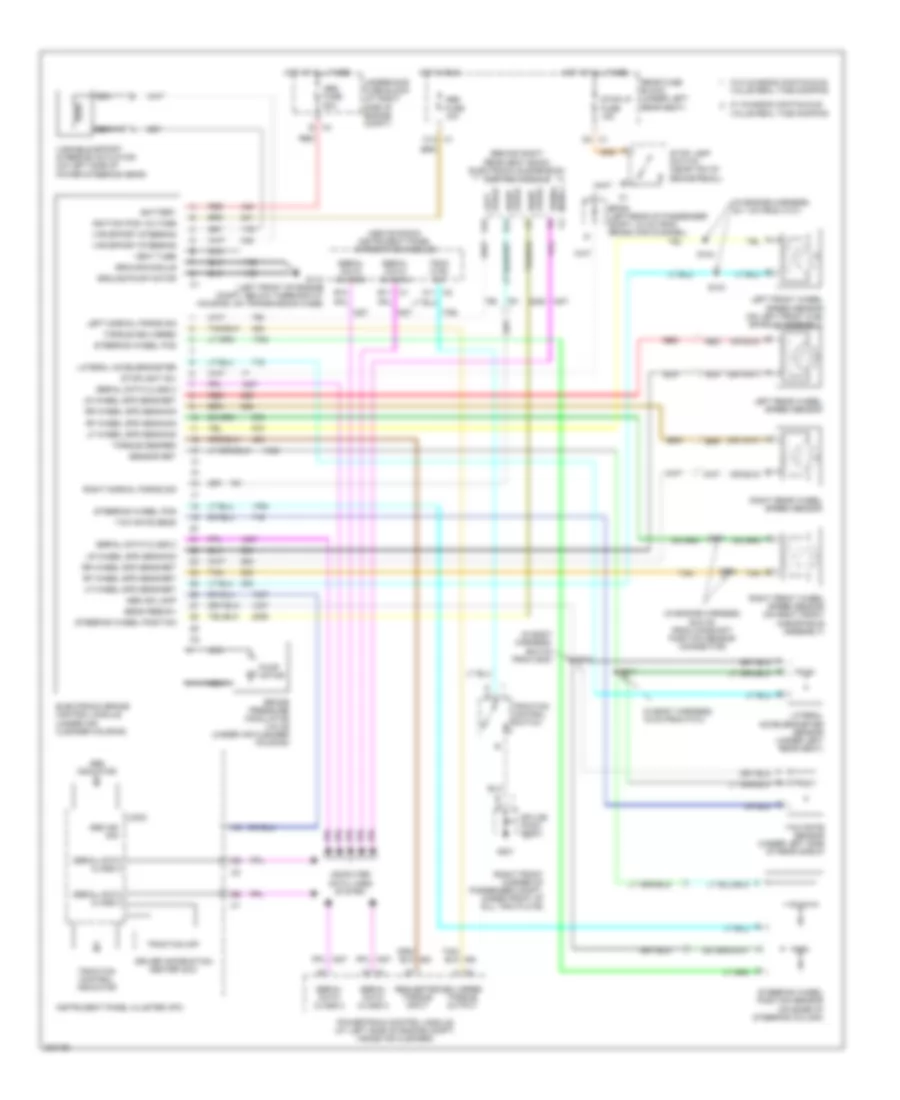
ANTI-LOCK BRAKES
Anti-lock Brakes Wiring Diagram for Cadillac DeVille DHS 2005
List of elements for Anti-lock Brakes Wiring Diagram for Cadillac DeVille DHS 2005:
- (above radio) instrument panel integration module
- (behind right rear seat back) electronic suspension control module
- (in body harness, 16 cm from p101)
- (in body harness, 66.5 cm from c200)
- (in engine harness, 25.9 cm from camshaft position sensor connector)
- (in engine harness, 54.1 cm from c101)
- (right front corner of passenger compt, under front of sill trim plate)
- A c
- Abs fuse 10a
- Abs fuse 50a
- Abs ind lamp
- Abs ind sig
- Abs indicator
- B c4
- B10
- Battery
- Brake pressure modulator valve (under air cleaner housing)
- C1 b11
- C1 c12
- C2 a11
- C5 c1
- Computer data lines system
- Delivered torque output
- Driver information center (dic)
- Electronic brake control module (under air cleaner housing)
- G110 (left front of engine compt, below thermostat housing, on transmission case)
- G201
- Ground-module
- Ground-pump motor
- Hot at all times
- Hot in run
- Ignition pos voltage
- Instrument panel cluster (ipc)
- Lateral accelerometer
- Lateral accelerometer sensor (under left rear seat)
- Left force d15
- Left front wheel speed sensor (on left front hub/ spindle assembly)
- Left normal force sig
- Left rear wheel speed sensor
- Lf wheel spd sens-ret
- Lf wheel spd sens-sig
- Logic
- Lr wheel spd sens-ret
- Lr wheel spd sens-sig
- Nca
- Powertrain control module (at left side of engine compt, inside air cleaner)
- Pump motor
- Rear fuse block (under left rear seat)
- Red
- Requested torque input
- Rf wheel spd sens-ret
- Rf wheel spd sens-sig
- Right force c7
- Right force d14
- Right front wheel speed sensor (on right front hub/spindle assembly)
- Right normal force sig
- Right rear wheel speed sensor
- Rr wheel spd sens-ret
- Rr wheel spd sens-sig
- S101
- S102
- S103
- S104
- S211
- S212
- Sens feed-5v
- Sensor ret
- Serial data class 2
- Serial data d4
- Sp308 (left rear of passenger compt, 24 cm from cross car channel)
- Splice pack sp201
- Steering wheel pos
- Steering wheel position
- Steering wheel position sensor (on base of steering column)
- Stop lamp switch (near top of brake pedal)
- Stop lp fuse 15a
- Stoplight sw
- Tan
- Torque delivered
- Torque desired
- Trac ctrl sw
- Traction control indicator
- Traction control switch
- Traction off
- Underhood fuse block (at right side of engine compt)
- Value real time damping
- Var effort steering
- Variable effort steering actuator (on left side of power steering gear)
- Vent tube
- W/ chassis continuous
- W/o chassis continuous
- Yaw rate sens
- Yaw rate sensor (under left side of rear shelf)
 English