ANTI-LOCK BRAKES
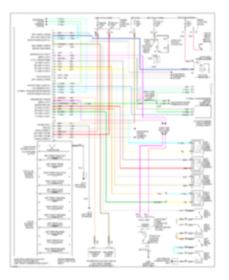
Anti-lock Brake Wiring Diagrams for Cadillac Seville STS 1999
List of elements for Anti-lock Brake Wiring Diagrams for Cadillac Seville STS 1999:
- (body harn, 10 cm from left rear door breakout)
- (left front corner of engine compartment)
- (left front of engine)
- (left rear of luggage compt) g404
- (top of brake pedal)
- 5 volt sensor feed
- Abs fuse 10a
- Abs mot fuse 40a
- Abs sol fuse 30a
- Abs/tcc switch
- Antilock indicator
- Battery power
- Brake pressure modulator valve (bpmv)
- Brake switch input
- Brake wear sens
- C11
- C12
- C302
- Computer data lines system
- Data lines
- Delivered torque
- Delivered torque output
- Disable input
- Electronic brake & traction control module (ebtcm) (left front corner of eng compt)
- Electronic power steering system
- Electronic suspension system
- G110
- G114 (left rear of engine)
- G300 (under left front seat)
- Ground
- Hot at all times
- Hot in acc or run
- Hot in on
- Ign 1
- Ign 1 fuse 10a
- Instrument panel cluster
- Instrument panel integration module (behind center of dash)
- Lateral accelerometer sensor
- Lateral accelerometer sensor (under left rear seat)
- Left front brake pad
- Left front hold valve solenoid
- Left front isolation valve solenoid
- Left front prime valve solenoid
- Left front release valve solenoid
- Left front wheel speed sensor
- Left normal force
- Left rear brake pad
- Left rear hold valve solenoid
- Left rear release valve solenoid
- Left rear wheel speed sensor
- Lf wss hi input
- Lf wss lo input
- Lr wss hi input
- Lr wss lo input
- Magna steer hi
- Magna steer lo
- Nca
- Pnk
- Power input
- Powertrain control module
- Pump motor
- Pump motor power output
- Pwm swps sig
- Rear junction block
- Red
- Requested torque
- Requested torque input
- Rf wss hi input
- Rf wss lo input
- Right front brake pad
- Right front hold valve solenoid
- Right front isolation valve solenoid
- Right front prime valve solenoid
- Right front release valve solenoid
- Right front wheel speed sensor
- Right rear brake pad
- Right rear hold valve solenoid
- Right rear release valve solenoid
- Right rear wheel speed sensor
- Rr wss hi input
- Rr wss lo input
- S300
- S301
- Sensor return
- Serial data
- Stop lp fuse 15a
- Stop- lamp/ btsi switch (top of brake pedal)
- Stoplamp switch capacitor
- Swps phase a (digital)
- Swps phase b (analog)
- Swps phase b (digital)
- Tan
- Tcs valve solenoid control signals
- Traction control disable switch
- Under- hood junction block
- Valve power output
- Valve solenoid control signals
- Yaw rate sensor (front center of rear compt)
- Yaw sensor input
 English