ANTI-LOCK BRAKES
Anti-lock Brakes Wiring Diagram (1 of 2) for Cadillac STS V 2006

List of elements for Anti-lock Brakes Wiring Diagram (1 of 2) for Cadillac STS V 2006:
- (on right front corner of engine compt, behind right front wheel) electronic brake control module (ebcm)
- 5-volt reference
- A10
- A11
- A12
- A13
- A14
- Abs fuse 15a
- Abs fuse 50a
- B + sol vlv cntrl
- B+ motor control
- B10
- B11
- B12
- B13
- B14
- Battery
- Brake fluid pressure sensor sig
- Brake pressure modulator valve (bpmv)
- C10
- Computer data lines system
- G104 (on right front frame rail, near bumper bracket)
- G110 (on right front frame rail, near right front strut tower)
- Ground
- Hi spd gmlan ser data +
- Hi spd gmlan ser data -
- Hi spd gmlan ser data w/u
- High effort ctrl
- Hot at all times
- Hot in run or start
- Ign 1
- Lateral accelerometer signal
- Left front inlet
- Left front iso- lation
- Left front outlet
- Left front prime
- Left rear inlet
- Left rear outlet
- Lf wheel speed sens low ref
- Lf wheel speed sens sig
- Long accelerometer signal
- Low effort ctrl
- Low reference
- Lr wheel speed sens low ref
- Lr wheel speed sens sig
- Pnk
- R43
- R44
- R45
- R46
- Rf wheel speed sens low ref
- Rf wheel speed sens sig
- Right front inlet
- Right front iso- lation
- Right front outlet
- Right front prime
- Right rear inlet
- Right rear outlet
- Rr wheel speed sens low ref
- Rr wheel speed sens sig
- Run/ crank relay
- S100
- Solenoid valves
- Steering wheel position sig a
- Steering wheel position sig b
- Tan
- Underhood fuse block (right front side of engine compt)
- Variable effort steering actuator (on left side of power steering gear)
- Yaw rate sensor signal
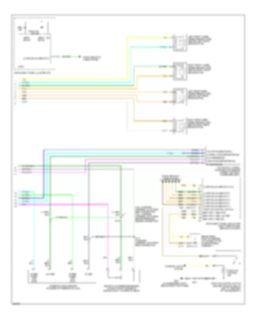
Anti-lock Brakes Wiring Diagram (2 of 2) for Cadillac STS V 2006
List of elements for Anti-lock Brakes Wiring Diagram (2 of 2) for Cadillac STS V 2006:
- (3.6l: in engine harness, 30 cm from ebcm connector) (4.6l: in engine harness, 25 cm from brake pressure sensor connector)
- (in passenger compt, behind right kick panel)
- 5v ref
- 5v reference
- Abs ind
- Brake fluid pressure sensor (in right front corner of engine compt, on rear of ebcm)
- Brake pedal position sensor (attached to top of brake pedal assembly)
- Computer data lines system
- Ebcm gmlan
- G201
- Hi spd gmlan ser data +
- Hi spd gmlan ser data -
- Hi spd gmlan ser data w/u
- Ign
- Instrument panel cluster (ipc)
- Instrument panel module (ipm) (right side of dash, behind glove box)
- Interior lights system
- Lateral accelerometer sig
- Left front wheel speed sensor (wss) (behind left front brake rotor)
- Left rear wheel speed sensor (wss) (behind left rear brake rotor)
- Lo spd gmlan ser data
- Logic
- Long accelerometer sig
- Low ref
- Low reference
- Right front wheel speed sensor (wss) (behind right front brake rotor)
- Right rear wheel speed sensor (wss) (behind right rear brake rotor)
- S117 (in engine harness, 36 cm from ebcm connector)
- S118
- S311
- Steer wheel pos sig a
- Steer wheel pos sig b
- Steering angle sensor (on base of steering column)
- Tan
- Traction control ind
- Traction control switch
- Traction control switch (center console, below and to the right of the gearshift)
- Traction off ind
- Yaw rate & lateral acceleration sensor (under the front passenger seat)
- Yaw rate sens signal