ANTI-LOCK BRAKES
Anti-lock Brakes Wiring Diagram, with VSC (1 of 2) for Cadillac STS V 2009

List of elements for Anti-lock Brakes Wiring Diagram, with VSC (1 of 2) for Cadillac STS V 2009:
- (left side of engine compt) auxiliary brake pump booster
- (not used)
- (on right front frame rail, near right front strut tower) g110
- 1-17
- 1-32
- 21-56
- 34-46
- 48-50
- 54-69
- Abs fuse 25a
- Abs mtr fuse 50a
- Batt positive volt
- Brake pressure modulator valve (bpmv)
- Brk vac pump fuse 15a (3.6l)
- Brk vac pump relay
- Can bus high serial data
- Can bus low serial data
- Computer data lines system
- Electronic brake control module (ebcm) (right front corner of engine compt)
- Electronic suspension control (esc) module (below right "c" pillar)
- Engine control module (ecm) (front of engine, on right valve cover)
- G110 (on right front frame rail, near right front strut tower)
- G201 (in passenger compt, behind right kick panel)
- G402 (in rear compt, to rear of left rear shock tower)
- Gnd
- Hi spd gmlan serial data (+)
- Hi spd gmlan serial data (-)
- Hot at all times
- Hot w/ pwr/trn relay energized
- Ign 1
- Instrument panel module (ipm)
- Interior lights system
- J311
- Jx404 (behind right side of rear seat back)
- Lf wheel spd sens low ref
- Lf wheel spd sens sig
- Lo spd gmlan serial data
- Lr wheel spd sens low ref
- Lr wheel spd sens sig
- Nca
- Pnk
- Rf wheel spd sens low ref
- Rf wheel spd sens sig
- Rr wheel spd sens low ref
- Rr wheel spd sens sig
- Serial data bus (+)
- Serial data bus (-)
- Serial data wake up
- Serial data wakeup
- Steering actr hi effort ctrl
- Steering actr lo effort ctrl
- Tan
- Traction control ind
- Traction control switch (tcs)
- Traction ctrl sw sig 2 x3
- Underhood fuse block (right front side of engine compt)
- Vacuum pump rly ctrl
- Variable effort steering actuator (in left rear engine compt, on steering rack)
- Vehicle stability control module (left rear wheel hub assembly)
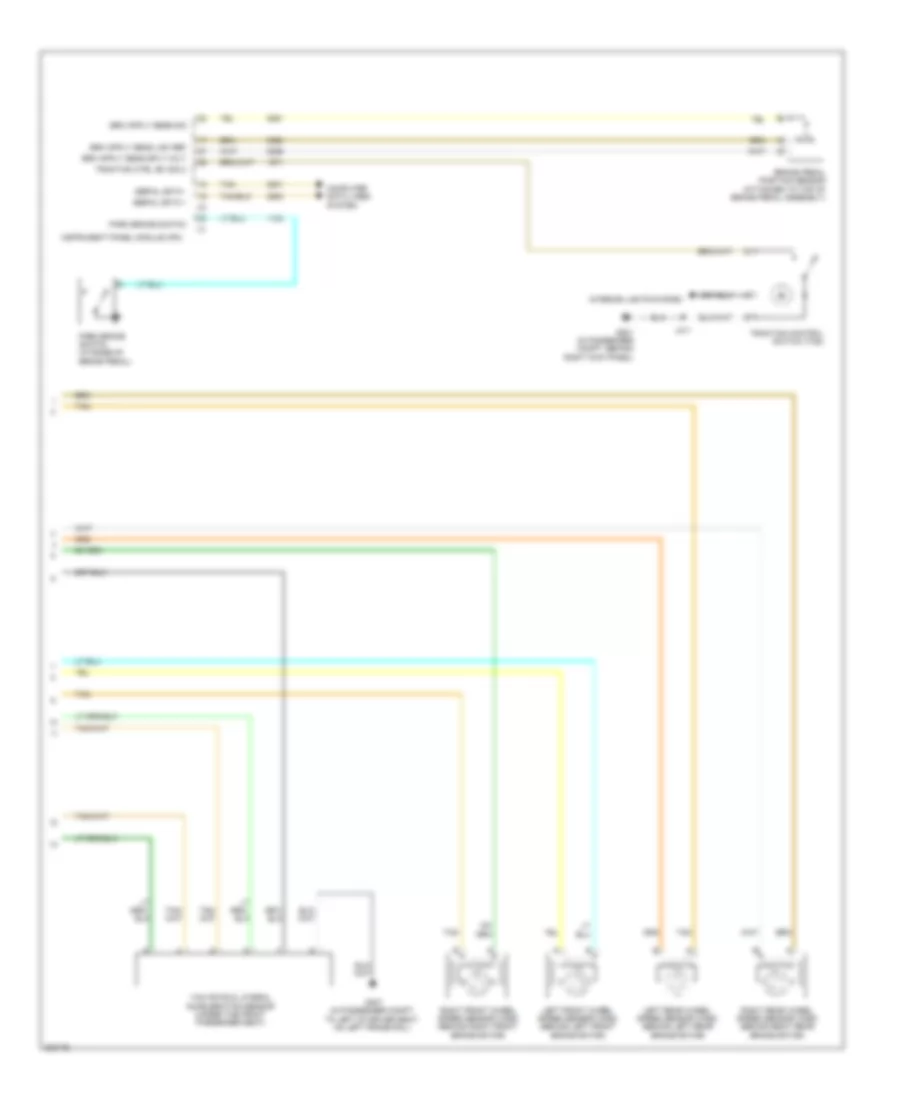
Anti-lock Brakes Wiring Diagram, with VSC (2 of 2) for Cadillac STS V 2009
List of elements for Anti-lock Brakes Wiring Diagram, with VSC (2 of 2) for Cadillac STS V 2009:
- (near left front strut tower, at bottom of inside fender well)
- Abs ind
- Brake fluid level switch (in master cylinder reservoir)
- Brake ind
- Can bus high
- Can bus low
- Computer data lines system
- Driver information center (dic) display
- G101
- G200 (in passenger compt, behind left kick panel)
- G307 (in passenger compt, to left of driver seat, on left frame rail)
- Gnd
- Hot at all times
- Hot w/ run relay energized
- Ign
- Ign 1 volt
- Instrument panel cluster (ipc)
- J/c
- Jx204 (under passenger side of dash, near g201)
- Left front wheel speed sensor (wss) (behind left front brake rotor)
- Left rear fuse block (under left side of rear seat)
- Left rear wheel speed sensor (wss) (behind left rear brake rotor)
- Logic
- Pnk
- Power steering control module (pscm) (left side of dash, above park brake pedal)
- Right front wheel speed sensor (wss) (behind right front brake rotor)
- Right rear wheel speed sensor (wss) (behind right rear brake rotor)
- Rim/rpa/isrvm/clm fuse 10a
- S10
- S22
- S23
- S24
- Serial data
- Steering wheel speed/position sensor (in passenger compartment, at base of steering column)
- Tan
- Traction off ind
- Tv/vics/ afs/scm fuse 10a
- Yaw & lateral accelerometer sensor
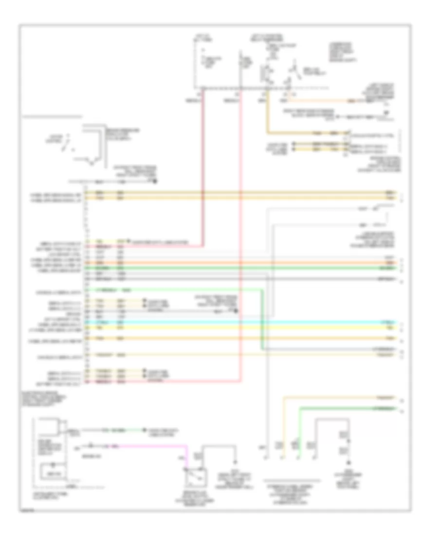
Anti-lock Brakes Wiring Diagram, without VSC (1 of 2) for Cadillac STS V 2009
List of elements for Anti-lock Brakes Wiring Diagram, without VSC (1 of 2) for Cadillac STS V 2009:
- (left side of engine compt) auxiliary brake booster pump
- (on right front frame rail, near right front strut tower) g110
- (right rear side of engine block, near starter) g112
- Abs fuse 25a
- Abs ind
- Abs mtr fuse 50a
- Act hi effort ctrl
- Battery positive volt
- Brake fluid level switch (in master cylinder reservoir)
- Brake ind
- Brake pressure modulator valve (bpmv)
- Brk vac pump fuse 15a (3.6l)
- Brk vac pump relay
- Can bus hi serial data
- Can bus lo serial data
- Computer data lines system
- Driver information center (dic) display
- Electronic brake control module (ebcm) (right front corner of engine compt)
- Engine control module (ecm) (front of engine, on right valve cover)
- G101 (near left front strut tower, at behind of inside fender well)
- G200 (in passenger compt, behind left kick panel)
- Ground
- Hot at all times
- Hot w/ pwr/trn relay energized
- Ign
- Instrument panel cluster (ipc)
- Lf wheel spd sens low ref
- Logic
- Low effort ctrl
- Motor control
- Nca
- Serial data
- Serial data (+) (1)
- Serial data (-) (1)
- Serial data bus (+)
- Serial data bus (-)
- Serial data wake up
- Steering wheel speed/ position sensor (in passenger compt, at base of steering column)
- Tan
- Underhood fuse block (right front side of engine compt)
- Vacuum pump rly ctrl
- Variable effort steering actuator (on left side of power steering gear)
- Wheel spd sens lo ref lr
- Wheel spd sens lo ref rr
- Wheel spd sens low ref rf
- Wheel spd sens sig lf
- Wheel spd sens sig rf
- Wheel spd sens signal lr
- Wheel spd sens signal rr
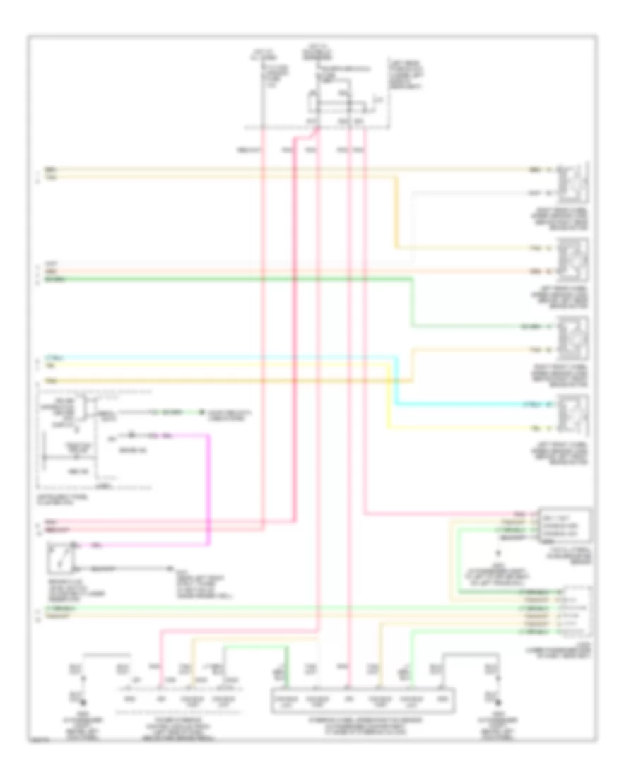
Anti-lock Brakes Wiring Diagram, without VSC (2 of 2) for Cadillac STS V 2009
List of elements for Anti-lock Brakes Wiring Diagram, without VSC (2 of 2) for Cadillac STS V 2009:
- Brake pedal position sensor (attached to top of brake pedal assembly)
- Computer data lines system
- G201 (in passenger compt, behind right kick panel)
- G307 (in passenger compt, to left of driver seat, on left frame rail)
- Instrument panel module (ipm)
- Interior lights system
- J311
- Left front wheel speed sensor (wss) (behind left front brake rotor)
- Left rear wheel speed sensor (wss) (behind left rear brake rotor)
- Park brake switch
- Park brake switch (at base of brake pedal)
- Right front wheel speed sensor (wss) (behind right front brake rotor)
- Right rear wheel speed sensor (wss) (behind right rear brake rotor)
- Serial data +
- Serial data -
- Tan
- Traction control switch (tcs)
- Traction ctrl sw sig 2
- Yaw rate & lateral acceleration sensor (under the front passenger seat)