ANTI-LOCK BRAKES
Anti-lock Brakes Wiring Diagram (1 of 2) for Cadillac XLR V 2006

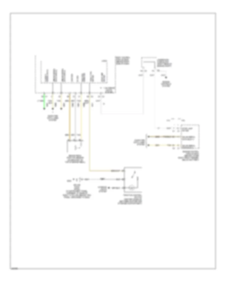
List of elements for Anti-lock Brakes Wiring Diagram (1 of 2) for Cadillac XLR V 2006:
- (engine harness, approximately 12 cm from ebcm breakout towards g105 breakout)
- 5v ref
- A10
- A11
- A12
- A13
- A14
- Abs fuse 27 60a
- Abs ind
- Abs/mrrtd fuse 1 10a
- Accelerometer lateral
- B +
- B10
- B11
- B12
- B13
- B14
- B16
- Bat
- Brake fluid level switch (left rear of engine compt, on brake fluid reservoir)
- Brake fluid pressure sensor (left front of engine compt, left side of bpmv valve)
- Brake ind
- Brk fluid lvl sens signal
- Brk fluid press sens sig
- C10
- C11
- C12
- C13
- C14
- Computer data lines system
- Electronic brake control module (ebcm) (left front of engine compartment)
- Electronic power steering system
- F10
- F11
- G101
- G105 (lower left side of engine, above generator)
- Gmlan
- Gmlan serial data (+)
- Gmlan serial data (-)
- Hot at all times
- Hot in on or start
- Ign 1 voltage
- Instrument panel cluster
- Ipc
- Ipc class 2 serial data
- Lateral accelerometer sig
- Left front wheel speed sensor (at left front hub assembly)
- Left rear wheel speed sensor (at left rear hub assembly)
- Lf spd sens low ref
- Lf wheel sens sig
- Logic
- Low ref
- Lr spd sens low ref
- Lr spd sens sig
- Message center
- Message request
- Pnk
- Power distribution system
- Rf spd sens low ref
- Rf spd sens sig
- Right front wheel speed sensor (at right front hub assembly)
- Right rear wheel speed sensor (at right rear hub assembly)
- Rr spd sens low ref
- Rr spd sens sig
- S191
- S193 (engine harness, approximately 10.5 cm from ebcm breakout towards g105 breakout)
- S195
- S238
- S244
- Sensor
- Sig grd
- Splice pack sp101 (in forward lamp harness, in engine compartment, on upper left frame rail, grounded to g101)
- Steering sol ctrl
- Steering wheel position sensor (base of steering column, under instrument panel)
- Strg sol voltage sply
- Strg whl pos sig a
- Strg whl pos sig b
- Strng wheel pos sig a
- Strng wheel pos sig b
- Tan
- Traction control ind
- Underhood fuse block (right rear of engine compt)
- Yaw & lateral accelerometer sensor (behind center of dash)
- Yaw rate sens sig
- Yaw rate sens sig (1)
Anti-lock Brakes Wiring Diagram (2 of 2) for Cadillac XLR V 2006
List of elements for Anti-lock Brakes Wiring Diagram (2 of 2) for Cadillac XLR V 2006:
- 4.4l
- 4.6l
- 5v ref
- Body control module (bcm) (behind right side of dash)
- Brake pedal position sensor (on bracket on top of brake pedal)
- Brk pos sens sig
- C3 a4
- C4 c4
- Class 2 serial data
- Computer data lines system
- Data bus (-) gmlan serial
- Engine control module (ecm) (behind lower right front fender, below battery)
- Engine controls system
- Exterior lights system
- G202
- Gmlan serial data bus (+)
- Gmlan serial data bus (-)
- Interior lights system
- Logic
- Low ref
- S246
- Splice pack sp202 (in instrument panel harness, at base of right "a" pillar, behind trim panel, grounded to g202)
- Stop lamp sw sig
- Sw sig stop lmp
- Tan
- Trac ctrl sw sig
- Traction control switch (center console, between shifter and storage compartment)
- Underhood fuse block (right rear of engine compt)