ANTI-LOCK BRAKES
Anti-lock Brakes Wiring Diagram (1 of 2) for Cadillac XLR V 2009

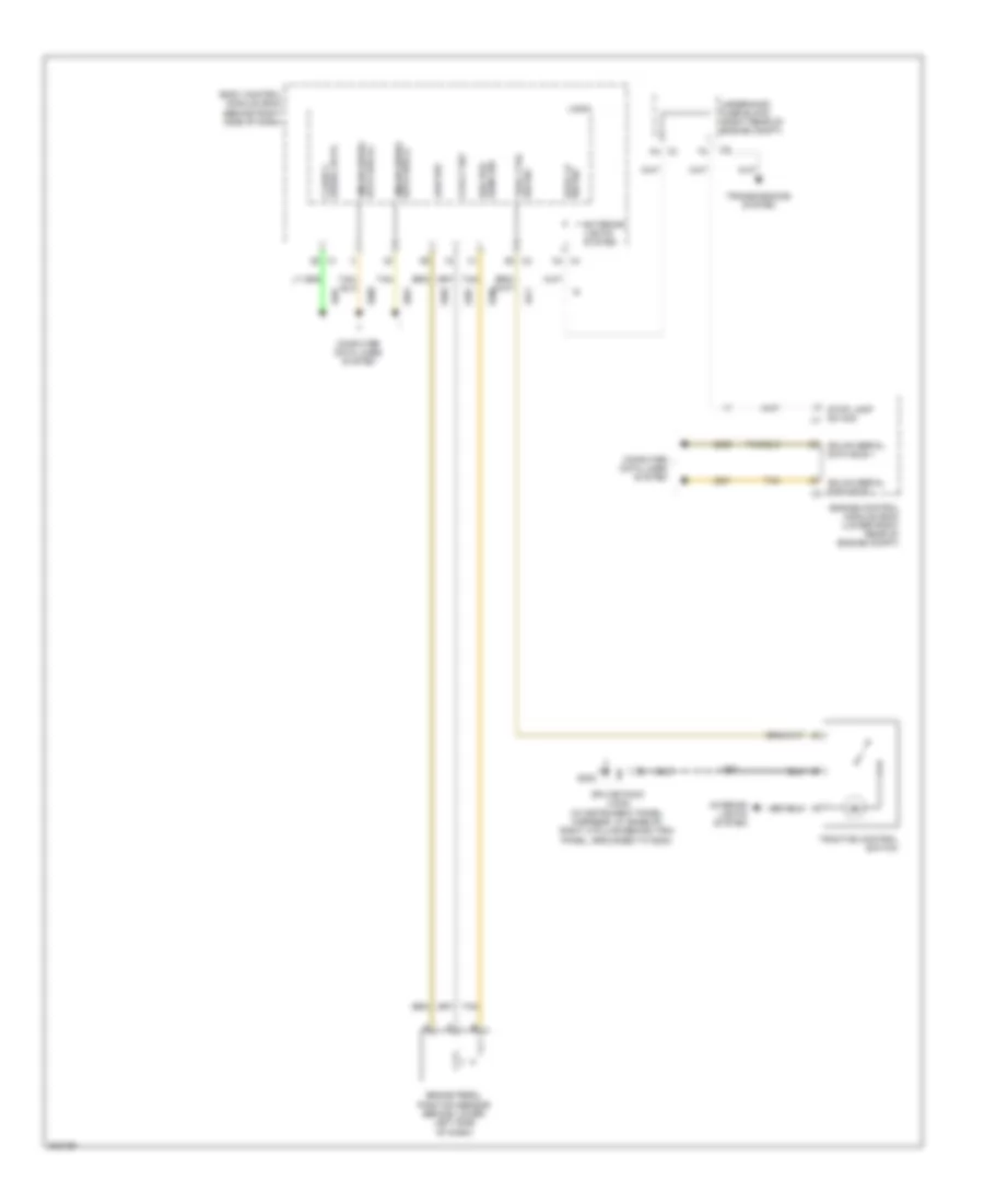
List of elements for Anti-lock Brakes Wiring Diagram (1 of 2) for Cadillac XLR V 2009:
- (lower left side of engine, above generator) g105
- Abs fuse 27 60a
- Abs ind
- Abs/mrrtd/afs fuse 1 10a
- Actr sply volt
- B15
- B16
- Brake fluid level switch (in brake fluid reservoir)
- Brake ind
- Brake pressure modulator valve (bpmv) (left front of engine compt)
- Brk fluid lvl sens signal
- Can bus hi serial data
- Can bus lo serial data
- Computer data lines system
- Driver information center (dic)
- Electronic brake control module (ebcm) (left front of engine compt)
- Electronic power steering system
- F10
- F11
- G101
- G105 (lower left side of engine, above generator)
- G201
- Gmlan serial data (+)
- Gmlan serial data (+) var effort steering actr ctrl
- Gmlan serial data (-)
- Ground
- Hot at all times
- Hot in on or start
- Ign 1 volt
- Instrument panel cluster (ipc)
- Ipc class 2 serial data
- J195
- J244
- J275
- Left front wheel speed sensor (wss) (at left front hub assembly)
- Left rear wheel speed sensor (wss) (at left rear hub assembly)
- Lf spd sens sig
- Logic
- Low ref
- Lr spd sens sig
- Park brake pedal assembly
- Pnk
- Power distribution system
- Red
- Rf spd sens sig
- Right front wheel speed sensor (wss) (at right front hub assembly)
- Right rear wheel speed sensor (wss) (at right rear hub assembly)
- Rr spd sens sig
- Serial data can bus hi
- Serial data can bus lo
- Signal park brake
- Splice pack jx101 (in forward lamp harness, in engine compt, on upper left frame rail, grounded to g101)
- Splice pack jx201 (in instrument panel harness, at base of left a pillar behind trim panel, grounded to g201)
- Steering angle sensor
- Tan
- Traction control off ind
- Underhood fuse block (right rear of engine compt)
- Var eff strg
- X1 a5
- Yaw & lateral accelerometer sensor (behind center of dash)
Anti-lock Brakes Wiring Diagram (2 of 2) for Cadillac XLR V 2009
List of elements for Anti-lock Brakes Wiring Diagram (2 of 2) for Cadillac XLR V 2009:
- 5-volt ref
- Body control module (bcm) (behind right side of dash)
- Brake pedal position sensor (behind lower left side of dash)
- Brk pos sens sig
- Class 2 serial data
- Computer data lines system
- Data bus (-) gmlan serial
- Engine control module (ecm) (lower right rear of engine compt)
- Exterior lights system
- G202
- Gmlan serial data bus (+)
- Gmlan serial data bus +
- Gmlan serial data bus - x3
- Interior lights system
- J246
- Logic
- Low ref
- Splice pack jx202 (in instrument panel harness, at base of right a pillar behind trim panel, grounded to g202)
- Stop lamp sw sig x1
- Stop lp sw sig
- Tan
- Trac ctrl sw sig
- Traction control switch
- Transmissions system
- Underhood fuse block (right rear of engine compt)
- X3 a4
- X4 c4