ANTI-LOCK BRAKES
Anti-lock Brake Wiring Diagrams, Commercial Chassis for Chevrolet Forward Control P12 1998

List of elements for Anti-lock Brake Wiring Diagrams, Commercial Chassis for Chevrolet Forward Control P12 1998:
- (ebcm harn, near right side of radiator)
- (i/p harn, above steering column)
- (i/p harn, left side of bulkhead)
- (left frame rail)
- (near steering column) data link connector
- (rear of left cylinder head)
- Abs ind
- Abs lamp control
- Brake diode d101 (underhood fuse-relay center)
- Brake ind
- Brake lamp control
- Brake pressure differential switch
- Brake sw input
- Brake sw output
- C1 tcc/ stoplamp switch
- Diesel
- Ebcm ground
- Electronic brake control module (below radiator of first crossmember)
- G100
- G114
- Gasoline
- Gauges fuse 8 20a
- Hot at all times
- Hot in run
- Hot in run or start
- I-3 fuse 15a
- I/p fuse block
- Ign
- Instrument cluster
- Left front wheel speed sensor
- Lft frt sensor (+)
- Lft frt sensor (-)
- Pnk
- Pump motor ground
- Pump motor power
- Red
- Right front wheel speed sensor
- Rt frt sensor (+)
- Rt frt sensor (-)
- S149 (i/p harn, 10 cm from before i/p fuse block breakout)
- S150
- S154
- S162
- S167
- S200
- Serial data line
- Serial data signal
- Tan
- Vehicle control module (left side of engine compt)
- Vehicle speed sig
- Vss buffer (left side of interior bulkhead)
- Vss sig
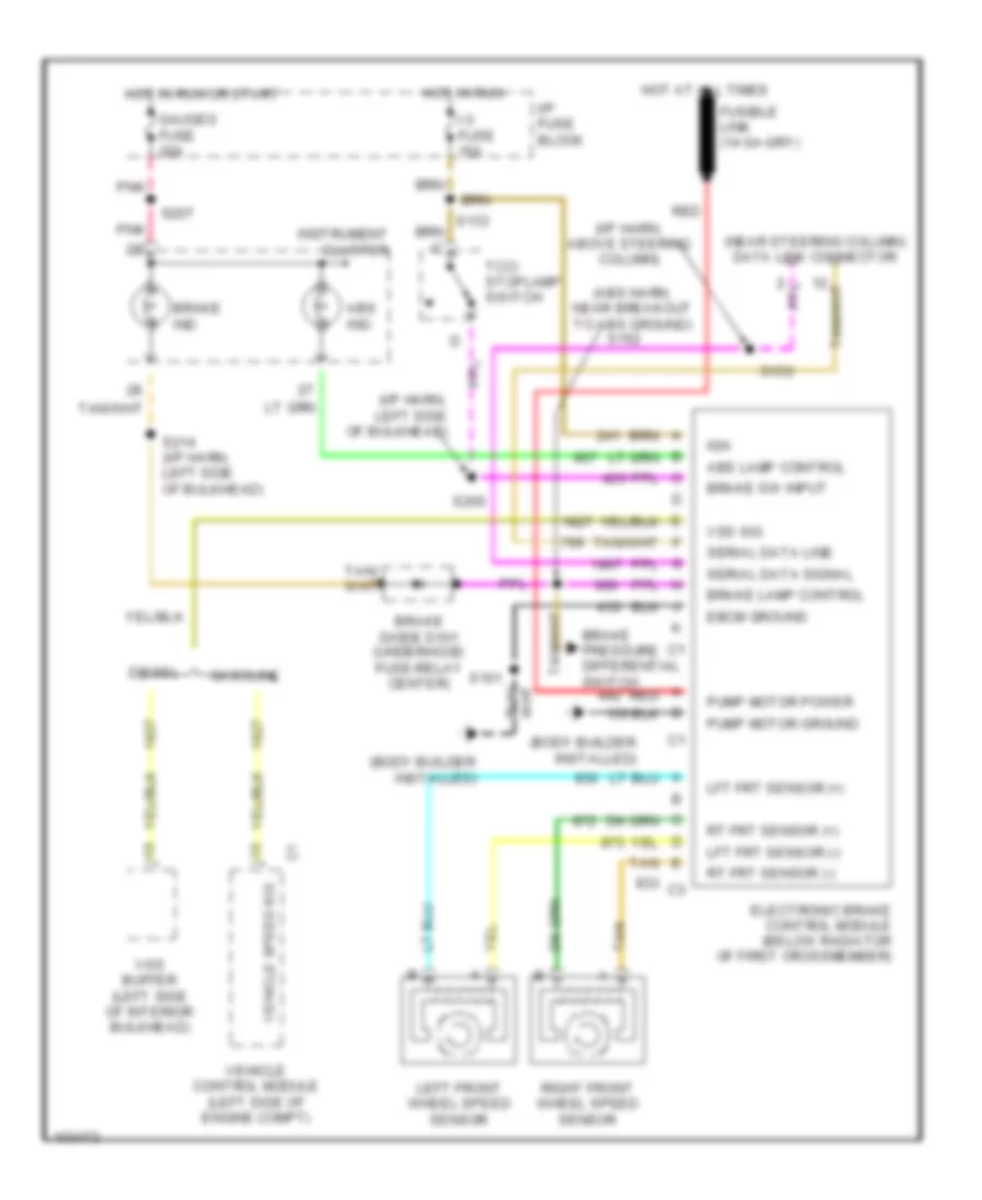
Anti-lock Brake Wiring Diagrams, Motor Home Chassis for Chevrolet Forward Control P12 1998
List of elements for Anti-lock Brake Wiring Diagrams, Motor Home Chassis for Chevrolet Forward Control P12 1998:
- (abs harn, near breakout to abs ground)
- (body builder installed)
- (i/p harn, above steering column)
- (i/p harn, left side of bulkhead)
- (near steering column) data link connector
- Abs ind
- Abs lamp control
- Brake diode d101 (underhood fuse-relay center)
- Brake ind
- Brake lamp control
- Brake pressure differential switch
- Brake sw input
- Diesel
- Ebcm ground
- Electronic brake control module (below radiator of first crossmember)
- Gasoline
- Gauges fuse 20a
- Hot at all times
- Hot in run
- Hot in run or start
- I-3 fuse 15a
- I/p fuse block
- Ign
- Instrument cluster
- Left front wheel speed sensor
- Lft frt sensor (+)
- Lft frt sensor (-)
- Pnk
- Pump motor ground
- Pump motor power
- Red
- Right front wheel speed sensor
- Rt frt sensor (+)
- Rt frt sensor (-)
- S150
- S161
- S162
- S200
- S207
- S214 (i/p harn, left side of bulkhead)
- Serial data line
- Serial data signal
- Tan
- Tcc/ stoplamp switch
- Vehicle control module (left side of engine compt)
- Vehicle speed sig
- Vss buffer (left side of interior bulkhead)
- Vss sig