ANTI-LOCK BRAKES
Anti-lock Brake Wiring Diagrams for Chevrolet Malibu 2000
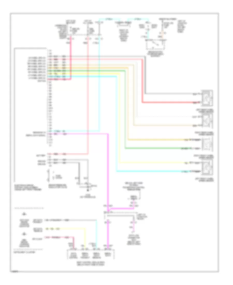
List of elements for Anti-lock Brake Wiring Diagrams for Chevrolet Malibu 2000:
- (below left side of dash) powertrain control module (pcm)
- A10
- A11
- A12
- A3 c3
- A7 c3
- Abs fuse 50a
- Abs ign fuse 10a
- Antilock brake warning indicator
- B10
- B11
- B7 c2
- Battery
- Body control module (bcm) (below right side of dash)
- Brake pressure modulator valve
- Brake sw in
- Brake switch (on brake pedal support)
- C10
- C11
- C3 b2
- D2 c1
- Data clock control
- Data link connector (dlc) (below left side of dash)
- E3 c1
- Electronic brake control module (ebcm) (inside left front fender)
- F12
- G129 (on transaxle)
- Ground
- Hot at all times
- Hot in on or start
- Ignition
- Instrument cluster
- Left front wheel speed sensor
- Left i/p junction block
- Left i/p junction block (on left end of dash)
- Left rear wheel speed sensor
- Lf wheel spd (hi)
- Lf wheel spd (lo)
- Lr wheel spd (hi)
- Lr wheel spd (lo)
- Nca
- Pnk
- Pump motor
- Red
- Red brake warning indicator
- Rf wheel spd (hi)
- Rf wheel spd (lo)
- Right front wheel speed sensor
- Right i/p junction block (on right end of dash)
- Right rear wheel speed sensor
- Rr wheel spd (hi)
- Rr wheel spd (lo)
- Serial data
- Serial data receive
- Serial data signal
- Serial data transmit
- Sp103
- Sp301 (2000)
- Sp302 (2001)
- Spi clock
- Spi data receive
- Spi data transmit
- Stop lps fuse 15a
- Tan
- Underhood junction block (on left side of engine compt)
 English