ANTI-LOCK BRAKES
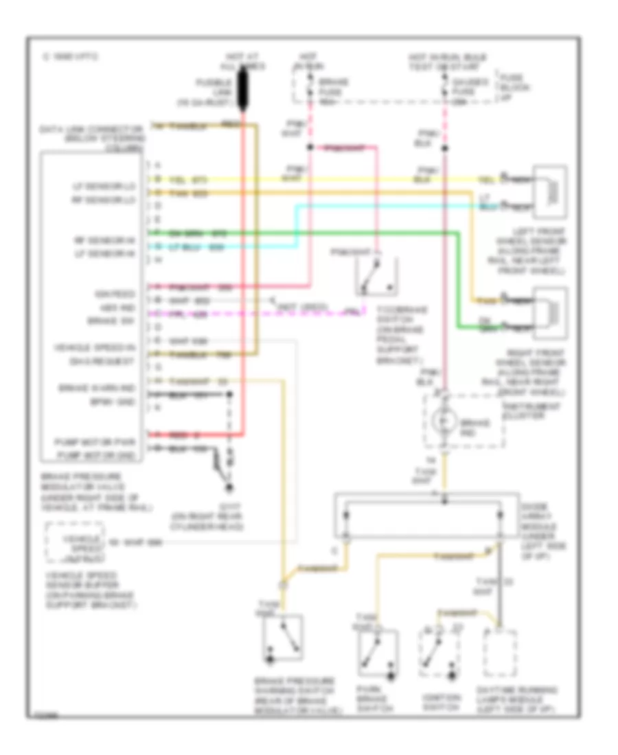
Anti-lock Brake Wiring Diagrams for Chevrolet Sportvan G30 1995
List of elements for Anti-lock Brake Wiring Diagrams for Chevrolet Sportvan G30 1995:
- (along frame
- (below steering
- (not used)
- (on right rear cylinder head)
- Abs ind
- B tan
- Bpmv gnd
- Bracket)
- Brake fuse 10a
- Brake ind.
- Brake pressure modulator valve (under right side of vehicle, at frame rail)
- Brake pressure warning switch (rear of brake modulator valve)
- Brake sw
- Brake warn ind
- C 1995 vftc
- Cluster
- Column)
- Data link connector
- Daytime running lamps module (left side of i/p)
- Diag request
- Diode array module (under left side of i/p)
- Front wheel)
- Fuse block: i/p
- Fusible link (16 ga-rust)
- G117
- Gauges fuse 20a
- Hot at all times
- Hot in run
- Hot in run, bulb test or start
- Ign feed
- Ignition switch
- Instrument
- Left front wheel sensor
- Lf sensor hi
- Lf sensor lo
- Nca
- Output
- Park brake switch
- Pnk/
- Pump motor gnd
- Pump motor pwr
- Rail, near left
- Rail, near right
- Red
- Rf sensor hi
- Rf sensor lo
- Right front wheel sensor
- Speed
- Tan
- Tan/
- Tcc/brake switch (on brake pedal support
- Vehicle
- Vehicle speed in
- Vehicle speed sensor buffer (on parking brake support bracket)
 English