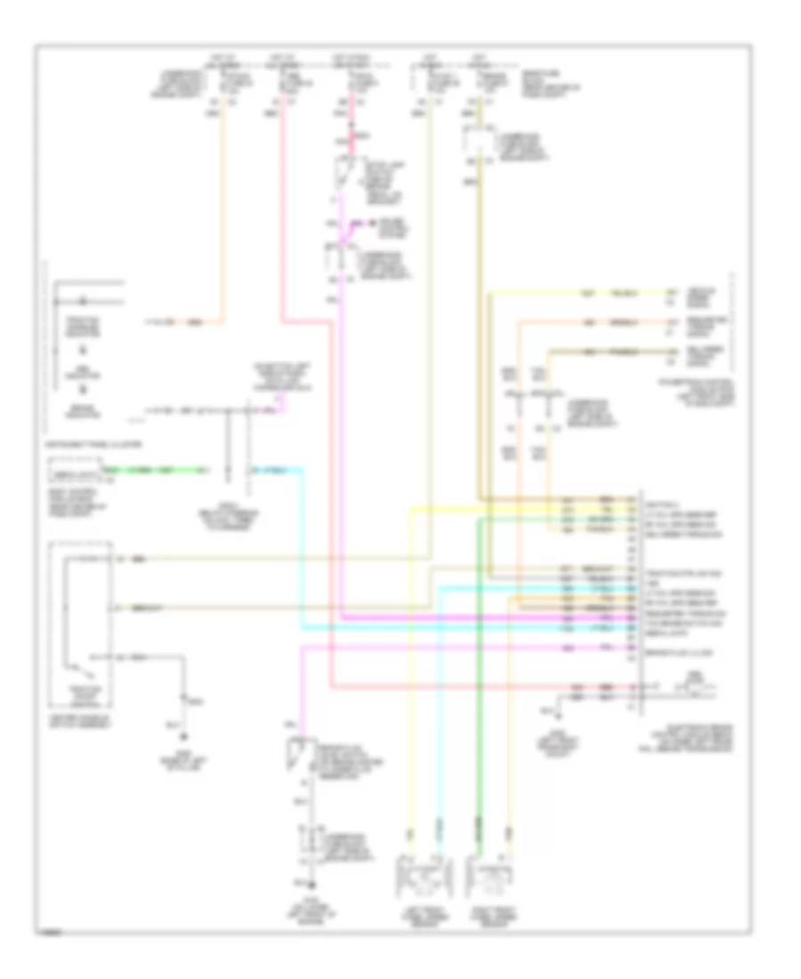
ANTI-LOCK BRAKES
Anti-lock Brakes Wiring Diagram for Chevrolet SSR 2004
List of elements for Anti-lock Brakes Wiring Diagram for Chevrolet SSR 2004:
- (on bottom left side of dash) data link connector (dlc)
- Abs fuse 48 60a
- Abs indicator
- Abs pump
- B10
- B12
- Body control module (bcm) (rear center of pass compt)
- Brake fluid level switch (on brake master cylinder fluid reservoir)
- Brake fluid lvl sig
- Brake fuse 51 10a
- Brake indicator
- C11
- Center console switch assembly
- Cruise control system
- Delivered torque sig
- Delivered torque signal
- Electronic brake control module (ebcm) (on inner left frame rail, beside transmission)
- G100 (on lower left front of engine)
- G300 (base of left "b" pillar)
- G400 (left front frame body mount)
- Hot at all times
- Hot in run
- Hot in run or start
- Hvac 1 fuse 39 10a
- Ign e fuse 9 10a
- Ignition 3
- Instrument panel cluster
- Ipc/dic fuse 24 10a
- Left front wheel speed sensor
- Lf whl spd sens ref
- Lf whl spd sens sig
- Pnk
- Powertrain control module (pcm) (left front side of eng compt)
- Rear fuse block (rear center of pass compt)
- Red
- Requested torque sig
- Requested torque signal
- Rf whl spd sens ref
- Rf whl spd sens sig
- Right front wheel speed sensor
- S202
- S203
- Serial data
- Sp201 (below steering column, taped to harness)
- Stop lamp switch (above brake pedal, on bracket)
- Tan
- Tcc brake switch sig
- Traction ctrl sw sig
- Traction disabled indicator
- Traction on/off switch
- Underhood fuse block (left side of engine compt)
- Vehicle speed signal
- Vss
 Русский