ANTI-LOCK BRAKES
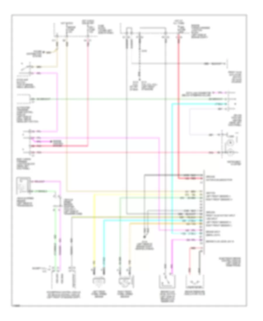
Anti-lock Brake Wiring Diagrams, New Style with Traction Control for Chevrolet Tahoe 2000

List of elements for Anti-lock Brake Wiring Diagrams, New Style with Traction Control for Chevrolet Tahoe 2000:
- A4 c1
- Abs fuse 60a
- Abs ind
- Body wiring harness junction block (near left kick panel)
- Brake fluid level sw in
- Brake fluid level switch (left side of brake fluid reservoir)
- Brake fuse 10a
- Brake in
- Brake ind
- Brake input
- Brake pressure modulator valve
- C8 a
- Data link connector (below steering column)
- Del torque
- Delivered torque
- Electronic brake control module (left side of inner frame)
- Engine wiring harness junction block (left side of engine compt)
- F6 c3
- F7 c2
- Fuse block (lower left side of dash)
- G102 (on left front body mount)
- G114 (left rear of engine)
- G200 (upper left kick panel)
- Ground
- Ground distribution system
- Hot at all times
- Hot in run
- Hot in run or start
- Ign 1 fuse 10a
- Ignition
- Instrument cluster
- Interior lights system
- Lamp active ctrl
- Lamp disable
- Left front sensor (+)
- Left front sensor (-)
- Left front wheel speed sensor
- Logic
- Low traction indicator
- Motor & solenoid pwr
- Nca
- Pnk
- Power distribution system
- Powertrain control module (left front of engine compt)
- Pump motor
- Red
- Req torque
- Requested torque
- Right front sensor (+)
- Right front sensor (-)
- Right front wheel speed sensor
- S102
- S202
- Serial data
- Sp203
- Splice pack (behind head- lamp switch)
- Stoplight switch (top of brake pedal bracket)
- Tan
- Trac sw input
- Traction assist switch
- Traction off indicator
- Vehicle speed sensor (left side of transmission/ transfer case)
- Vss high
- Vss input
- Vss low
- Vss out
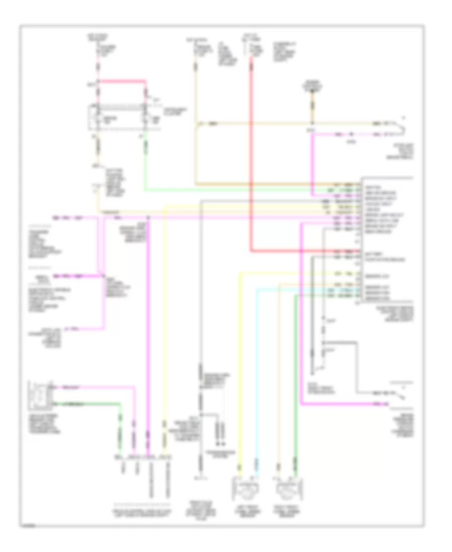
Anti-lock Brake Wiring Diagrams, New Style without Traction Control for Chevrolet Tahoe 2000
List of elements for Anti-lock Brake Wiring Diagrams, New Style without Traction Control for Chevrolet Tahoe 2000:
- 4.3l
- A4 c1
- Abs fuse 60a
- Automated transfer case control module (left side of dash, above headlight switch)
- Body wiring harness junction block (near left kick panel)
- Brake fluid level sw in
- Brake fluid level switch (left side of brake fluid reservoir)
- Brake fuse 10a
- Brake input
- Brake pressure modulator valve
- C11
- C8 a
- Data link connector (below steering column)
- Electronic brake control module (left side of inner frame)
- Engine control system
- Engine wiring harness junction block (left side of engine compt)
- Except 4.3 l
- F6 c3
- F7 c2
- Front axle act/sw input
- Front axle actuator/ switch (on axle housing)
- Fuse block (lower left side of dash)
- G110 (4.8l, 5.3l, 6.0l) (left front of engine)
- G116 (left rear of engine compt, near bulkhead)
- G119 (4.3l) (rt frt of eng)
- Ground
- Hot at all times
- Hot in run
- Hot in run and start
- Ign 1 fuse 10a
- Ignition
- Instrument cluster
- Left front sensor (+)
- Left front sensor (-)
- Left front wheel speed sensor
- Logic
- Motor & solenoid pwr
- Nca
- Pnk
- Power distribution system
- Powertrain control module or vehicle control module (left front of engine compt)
- Pump motor
- Red
- Right front sensor (+)
- Right front sensor (-)
- Right front wheel speed sensor
- S102
- Serial data
- Splice pack 205 center (near left kick panel)
- Stoplamp switch (top of brake pedal bracket)
- Tan
- Vehicle speed sensor (left rear of transmission)
- Vehicle speed sensor adapter (4wd only) (left side of transfer case)
- Vss high
- Vss input
- Vss low
- Vss output
Anti-lock Brake Wiring Diagrams, Old Style for Chevrolet Tahoe 2000
List of elements for Anti-lock Brake Wiring Diagrams, Old Style for Chevrolet Tahoe 2000:
- (engine harn, near ebcm breakout) s111
- (selectable 4wd harn, near breakout to transfer case relay)
- 4wd sw input
- Abs fuse 60a
- Abs ind
- Abs ind ground
- Battery
- Brake fuse 18 10a
- Brake ind
- Brake ind input
- Brake lamp ind out
- Brake pressure warning switch (underside of ebcm)
- Brake sw input
- Brake sw output
- Data link connector (dlc) (left of steering column)
- Daytime running lamp (drl) module (behind left side of dash)
- Ebcm ground
- Electronic brake control module (left side of engine compt)
- Electronic variable orifice (evo)/ passlock control module (under center of dash)
- Engine controls system
- Front axle actuator (on right rear of front drive axle)
- Fuse/relay block (left rear of engine compt)
- G119 (right front of eng block)
- Gauges fuse 4 10a
- Hot at all times
- Hot in run
- Hot in run or start
- I/p fuse block (under left side of dash)
- Ignition
- Instrument cluster
- Left front wheel speed sensor
- M/t
- Pnk
- Pump motor ground
- Red
- Right front wheel speed sensor
- S107
- S147
- S150 (engine harn, approx 13 cm from ebcm breakout)
- S151
- S152
- S213
- S280 (i/p harn, approx 5 cm from dlc breakout)
- S314
- Sensor high
- Sensor low
- Serial data
- Serial data line
- Stoplamp switch (top of brake pedal)
- Tan
- Transfer case control module (on steering column support bracket)
- Transmissions system
- Vehicle control module (vcm) (left side of engine compt)
- Vehicle speed sensor (vss) (left side of transmission/ transfer case)
- Vehicle speed sig
- Vss (+)
- Vss (-)
- Vss sig