ANTI-LOCK BRAKES
Anti-lock Brake Wiring Diagrams for Chevrolet Tracker 1998
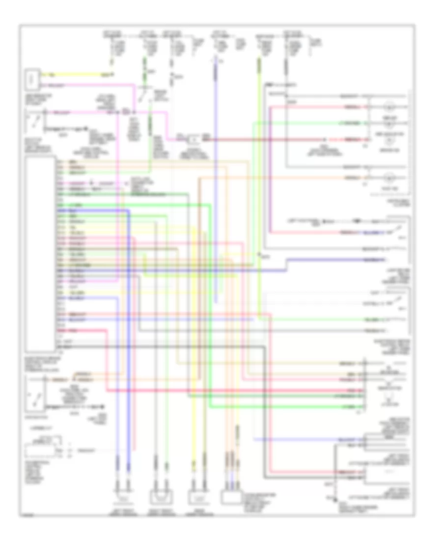
List of elements for Anti-lock Brake Wiring Diagrams for Chevrolet Tracker 1998:
- "4wd" ind
- (i/p harn, near left front speaker) s211
- (left kick panel) g200
- (main harn, near abs control module)
- (main harn, right side of dash)
- 4 speed a/t
- 4wd switch
- Abs active ind
- Abs fuse 50a
- Abs ind
- Abs motor pack assembly (left rear of engine compt)
- Abs resistor (right side of dash)
- Accelerometer (4wd only) (below front of center console)
- Brake ind
- Brake light switch
- C10
- C11
- C12
- C13
- C14
- C15
- C16
- D10
- D11
- D12
- D13
- D14
- D15
- D16
- Data link connector (obd-ii) (right of steering column)
- Diode 2 (behind dash, taped to harn)
- Electronic brake control module (right of steering column)
- Electronic brake control relay (left inner fender panel)
- Fuse box
- Fuse box 2
- G101 (right inner fender, near battery)
- G200 (left kick panel)
- Hot at all times
- Hot in on
- Hot in on or start
- Ig-coil meter fuse 15a
- Instrument cluster
- Lamp driver relay (left inner fender panel)
- Left front abs solenoid (attached to motor assembly)
- Left front speed sensor
- Lf motor
- M/t & 3 speed a/t
- Main fuse box
- Pnk
- Powertrain control module (left of steering column)
- Rear defg fuse 15a
- Rear motor
- Rear speed sensor
- Rf motor
- Right front speed sensor
- S108
- S132
- S208
- S209
- S213
- S251
- S260 (main harn, near blower switch)
- S270
- S271
- S272
- S275
- S278
- S280 (main harn, 3cm from pcm connectors breakout)
- S281 (main harness, left side of dash)
- S298
- Shuttle switch (left rear of engine compt)
- Stop horn fuse 15a
- Tail dome fuse 15a
- Turn back fuse 15a
 English