ANTI-LOCK BRAKES
Anti-lock Brakes Wiring Diagram for Chrysler 300M 2003
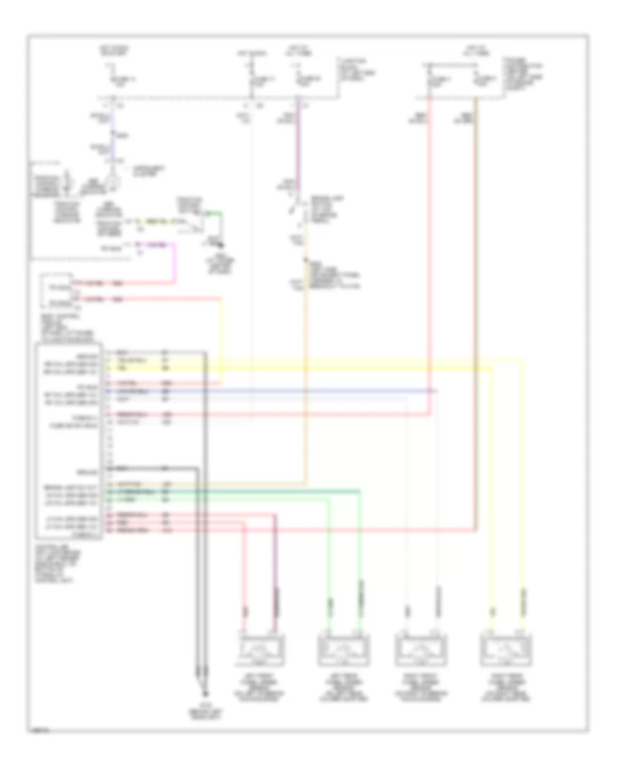
List of elements for Anti-lock Brakes Wiring Diagram for Chrysler 300M 2003:
- (at lower center of dash)
- A10
- A20
- Abs warning indicator
- Body control module (left end of dash, attached to junction block)
- Brake lamp sw out
- Brake lamp switch (at top of brake pedal)
- Controller anti-lock brake (at left fender side shield, on bottom of hydraulic control unit)
- D25
- F20
- Fuse 14 10a
- Fuse 17 10a
- Fuse 20 20a
- Fuse b (+)
- Fuse h 30a
- Fuse ign sw (run)
- Fuse k 40a
- G103 (behind left headlight)
- G201
- Ground
- Hot at all times
- Hot in run
- Hot in run or start
- Instrument cluster
- Junction block (at left end of dash)
- L50
- Left front wheel speed sensor (on left steering knuckle boss)
- Left rear wheel speed sensor (on left rear caliper adapter)
- Lf whl spd sen 12v
- Lf whl spd sen sig
- Lr whl spd sen 12v
- Lr whl spd sen sig
- Pci bus
- Power distribution center (on left side of engine compt)
- Red
- Rf whl spd sen 12v
- Rf whl spd sen sig
- Right front wheel speed sensor (on right steering knuckle boss)
- Right rear wheel speed sensor (on right rear caliper adapter)
- Rr whl spd sen 12v
- Rr whl spd sen sig
- S200
- S205 (left side instrument panel harness, in breakout to c140)
- Traction control sw sens
- Traction control switch
- Traction control warning indicator
 English