ANTI-LOCK BRAKES
Anti-lock Brake Wiring Diagrams for Dodge Avenger ES 1995
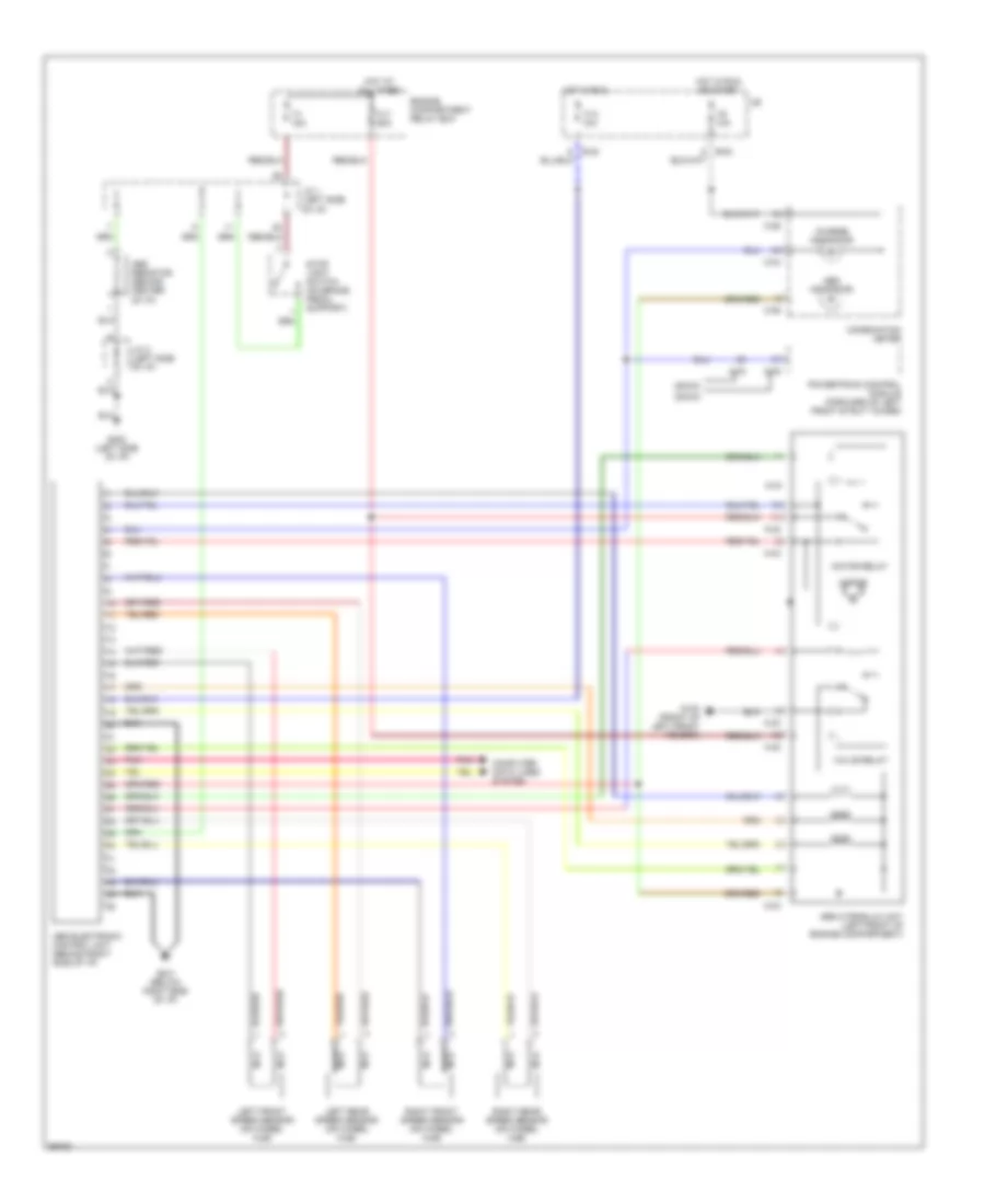
List of elements for Anti-lock Brake Wiring Diagrams for Dodge Avenger ES 1995:
- (dohc)
- (sohc)
- A-32
- A-33
- A-76
- A-78
- Abs electronic control unit (behind right side of i/p)
- Abs hydraulic unit (left front of engine compartment)
- Abs indicator
- Abs resistor (behind center of i/p)
- B-54
- C-04
- C-06
- Charge indicator
- Combination meter
- Computer data lines system
- Engine compartment relay box
- F1 15a
- F13 10a
- F8 10a
- Fl7 60a
- G100 (front of left front fender)
- G201 (below right side of i/p)
- G202 (left side of i/p)
- Hot at all times
- Hot in run
- Hot in run or start
- J/b
- J/c 1 (left side of i/p)
- J/c 2 (left side of i/p)
- Left front speed sensor (on wheel hub)
- Left rear speed sensor (on wheel hub)
- Motor
- Motor relay
- Nca
- Pnk
- Powertrain control module (forward of left front strut tower)
- Right front speed sensor (on wheel hub)
- Right rear speed sensor (on wheel hub)
- Stop light switch (on brake pedal support)
- Valve relay
 English