ANTI-LOCK BRAKES
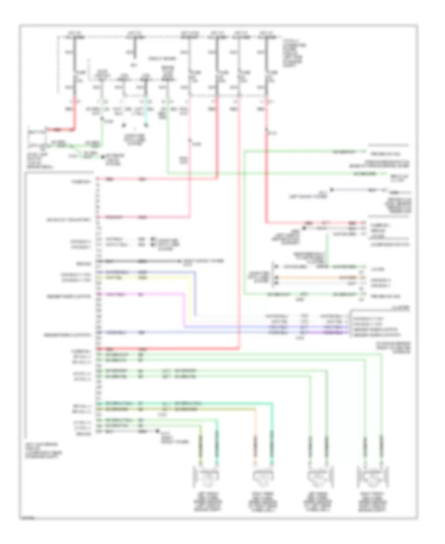
Anti-lock Brakes Wiring Diagram for Dodge Avenger Express 2010
List of elements for Anti-lock Brakes Wiring Diagram for Dodge Avenger Express 2010:
- (near breakout to instrument cluster) s260
- (right shock tower) g110
- A921
- A922
- Abs/esp snsr clstr fd
- Abs/esp snsr clstr rtn
- Anti-lock brake module (lower right rear of engine compt)
- B(+)
- B20
- Batt fd
- Brake fluid level sensor (brake fluid reservoir)
- Brake fluid level signal
- Brk flud lvl sw
- C104
- C11
- C114
- C200
- Can bus (+)
- Can bus (+) yaw
- Can bus (-)
- Can bus (-) yaw
- Circuit board
- Cluster
- Computer data lines system
- D464
- D465
- D64
- D65
- Dynamics sensor (front of center console)
- Exterior lights system
- F202
- Fuse 10a
- Fuse 30a
- Fuse 40a
- Fused b(+)
- G110 (right shock tower)
- G111 (left shock tower)
- G250 (left side of center stack support)
- G94
- Gnd
- Ground
- Hot at all times
- Hot in on or start
- Ign sw out (run-start)
- Left front abs wheel speed sensor (left side of engine compt)
- Left rear abs wheel speed sensor (at left rear wheelwell)
- Lf whl (+)
- Lf whl (-)
- Lin ccn
- Lower bank switch
- Lr whl (+)
- Lr whl (-)
- Nca
- Parking brake switch (base of parking brake lever)
- Prk brk sw sig
- Red
- Rf whl (+)
- Rf whl (-)
- Right front abs wheel speed sensor (right side of engine compt)
- Right rear abs wheel speed sensor (at right rear wheelwell)
- Rr whl (+)
- Rr whl (-)
- S110
- S126
- S129
- Stop lamp sw out
- Stop lamp switch (top of brake pedal)
- Stp lmp
- Totally integrated power module (left side of engine compt)
- Z905
 English