ANTI-LOCK BRAKES
Anti-lock Brake Wiring Diagrams for Dodge Grand Caravan EX 2001
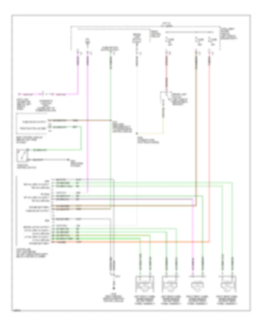
List of elements for Anti-lock Brake Wiring Diagrams for Dodge Grand Caravan EX 2001:
- 20a
- 25a
- 40a
- A107
- A111
- B27
- Body control module (behind left side of dash)
- Brake lamp switch (left side of brake pedal bracket)
- Brake lamp switch output
- Brake lmp sw output
- Controller anti-lock brake (on left side of eng compt, below master cylinder)
- D25
- Data link connector (below left side of dash)
- Diagnostic junction port (lower left of steering column)
- F500
- Front control module
- Fuse
- Fuse ign sw output
- Fuse ignition switch output
- G100 (body ground, near powertrain control module)
- G201 (rightside of dash)
- Gnd
- Hot at all times
- Intelligent power module (left side of engine compt)
- L50
- Left front wheel speed sensor (on left front wheel assembly)
- Left rear wheel speed sensor (on left rear wheel assembly)
- Lf whl spd 12v suply
- Lf whl spd sig
- Lr whl spd 12v suply
- Lr whl spd sig
- Pci bus
- Power (battery)
- Rf whl spd 12v suply
- Rf whl spd sig
- Right front wheel speed sensor (on right front wheel assembly)
- Right rear wheel speed sensor (on right rear wheel assembly)
- Rr whl spd 12v suply
- Rr whl spd sig
- S131 (eng harn, near breakout to transmission control module)
- S141
- S304 (in rear floor pan truck wiring)
- Tan/red
- Traction control switch
- Traction ctrl sw sen
- Z107
- Z127
 English