ANTI-LOCK BRAKES
Anti-lock Brake Wiring Diagrams for Dodge Neon 1999
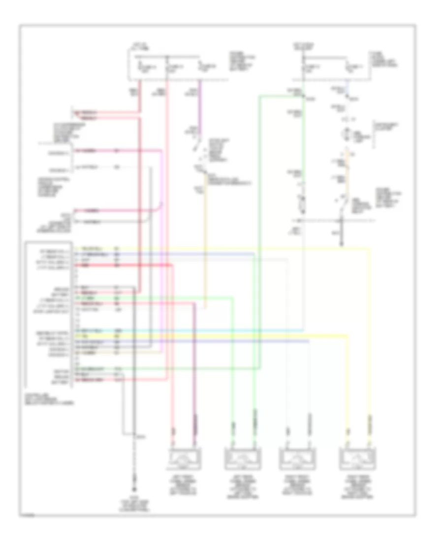
List of elements for Anti-lock Brake Wiring Diagrams for Dodge Neon 1999:
- A/c compressor clutch relay (in power distribution center)
- A10
- A17
- Abs relay cntrl
- Abs warning indicator relay
- Abs warning lamp
- Air bag control module (under rear of center console)
- B58
- Battery
- Ccd bus (+)
- Ccd bus (-)
- Controller anti-lock brake (below master cylinder)
- Data link connector (at left side of steering column)
- F12
- Fuse 10 15a
- Fuse 10 40a
- Fuse 11 5a
- Fuse 18 20a
- Fuse 25 15a
- Fuse block (under left side of dash)
- G100 (top left side of radiator closure panel)
- Ground
- Hot at all times
- Hot in run or start
- Ignition
- Instrument cluster
- L50
- Left front wheel speed sensor (attached to left knuckle)
- Left rear wheel speed sensor (attached to left disc brake adapter)
- Lt ft whl spd (+)
- Lt ft whl spd (1)
- Lt rear whl (+)
- Lt rear whl (-)
- Power distribution center (at rear of battery)
- Red
- Right front wheel speed sensor (attached to right knuckle)
- Right rear wheel speed sensor (attached to right disc brake adapter)
- Rt ft whl spd (+)
- Rt ft whl spd (-)
- Rt rear whl (+)
- Rt rear whl (-)
- S101 (near data link connector breakout)
- S108
- S109
- S219
- Stop lamp sw out
- Stoplight switch (top of brake pedal support)
 English