ANTI-LOCK BRAKES
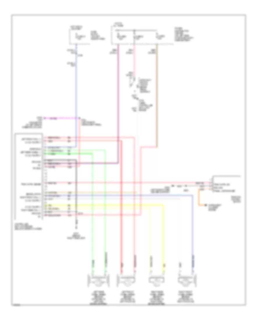
Anti-lock Brake Wiring Diagrams for Dodge Neon ES 2000
List of elements for Anti-lock Brake Wiring Diagrams for Dodge Neon ES 2000:
- A10
- A20
- B27
- Brake lmp sw
- Controller anti-lock brake (below master cylinder)
- D25
- Data
- F12
- Fuse 10 15a
- Fuse 23 15a
- Fuse 5 20a
- Fuse 8 40a
- Fuse block (on left side of dash)
- G107 (behind right headlamp)
- G202 (left side of dash center support)
- Ground
- Hot at all times
- Hot in run or start
- Instrument cluster system
- L50
- Left front wheel speed sensor (attached to left knuckle)
- Left front whl (-)
- Left rear wheel (-)
- Left rear wheel speed sensor (attached to left disc brake adapter)
- Link connector (at left side of steering column)
- Panel lamps driver
- Pci bus
- Power distribution center (on left side of engine compt, near battery)
- Red
- Right front wheel speed sensor (attached to right knuckle)
- Right front whl (-)
- Right rear wheel speed sensor (attached to right disc brake adapter)
- Right rear whl (-)
- S104 (left side of instrument panel)
- S108 (near controller anti-lock brake)
- S109
- S119
- S202
- Start/run
- Stoplight switch (top of brake pedal support)
- Trac cntrl sense
- Trac cntrl sw
- Traction control switch
 English