ANTI-LOCK BRAKES
Anti-lock Brake Wiring Diagrams for Dodge Neon High Line 1995
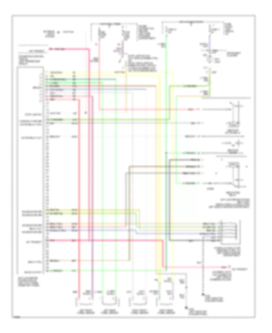
List of elements for Anti-lock Brake Wiring Diagrams for Dodge Neon High Line 1995:
- (+)
- (-)
- (lt)
- (rt)
- Abs fuse 40a
- Abs pump motor
- Abs pump motor relay
- Abs system relay
- Anti- lock
- Anti-lock brake system module (left cowl panel under inst panel)
- Anti-lock brake system relay box (near hydraulic modulator, left side of engine compartment)
- B116
- B120
- B142
- B143
- B146
- B148
- B47
- B57
- C224
- C227
- D21
- Diode
- Exterior lights system
- F18
- Fuse block (left side of i/p)
- Fuse 10 15a
- Fuse 11 5a
- G100 (left radiator closure panel)
- G19
- Ground
- Hot at all times
- Hot in run or start
- Hydraulic modulator (near relay box, on left side of engine compartment)
- Ign sw output
- Instrument cluster
- L50
- Left front wheel sensor
- Left rear wheel sensor
- Motor relay ctrl
- Motor relay out
- Pnk
- Pnk
- Power distribution center (left side of engine compartment)
- Powertrain control module (left fender side shield)
- Red
- Red
- Relay ctrl
- Relay out
- Right front wheel sensor
- Right rear wheel sensor
- Sci transmit
- Solenoid driver
- Stop lamp fuse 15a
- Stop lamp sw
- Stop lamp switch (w/o vehicle speed ctrl) or stop lamp & vehicle speed control switch (w/vehicle speed ctrl) (on top of brake pedal)
- Universal data link connector (left side of steering column)
- Warning lp driver
- Z12
 English