ANTI-LOCK BRAKES
Anti-lock Brakes Wiring Diagram for Dodge Pickup R2500 2004
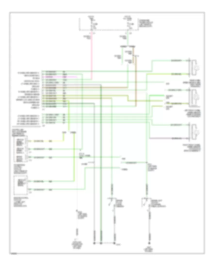
List of elements for Anti-lock Brakes Wiring Diagram for Dodge Pickup R2500 2004:
- (left side
- 4wabs
- 5.7l & w/ all wheel abs
- A111
- All times
- B20
- B22
- B222
- B29
- Brake fluid level sensor
- Brake fluid level sw sns
- Brake lamp switch (on brake pedal support)
- Brake sw sense
- Brake switch signal
- Controller anti-lock brake (left rear of engine compt)
- D25
- Data link connector (left side of dash)
- Diesel
- Engine control module (lower left front of engine block)
- Etc
- Except etc
- F500
- Fuse 10a
- Fuse 40a
- Fuse b (+)
- G104
- G201
- Gas
- Ground
- Hot at
- Hot in
- Ignition sw (run)
- Integrated power module (left rear of engine compt)
- Left front wheel speed sensor (rear of engine compartment)
- Lf wheel spd sensor (+)
- Lf wheel spd sensor (-)
- Lf wheel spd sns (+)
- Of dash)
- Pci bus
- Powertrain control module (right rear of engine compt)
- R wheel spd sensor (+)
- R wheel spd sensor (-)
- Rear wheel speed sensor (abs) (right rear frame rail)
- Rf wheel spd sensor (+)
- Rf wheel spd sensor (-)
- Right front wheel speed sensor (on knuckle spindle assembly)
- Run
- Rwabs
- S114
- S121 (left side of engine compt)
- S232 (left side of engine compt)
- Vehicle spd sig 2
- Vehicle speed sensor signal
- Vehicle speed sig
- Vehicle speed signal 2
- Z107
- Z127
 English