ANTI-LOCK BRAKES
Anti-lock Brake Wiring Diagrams for Dodge Pickup R3500 1998
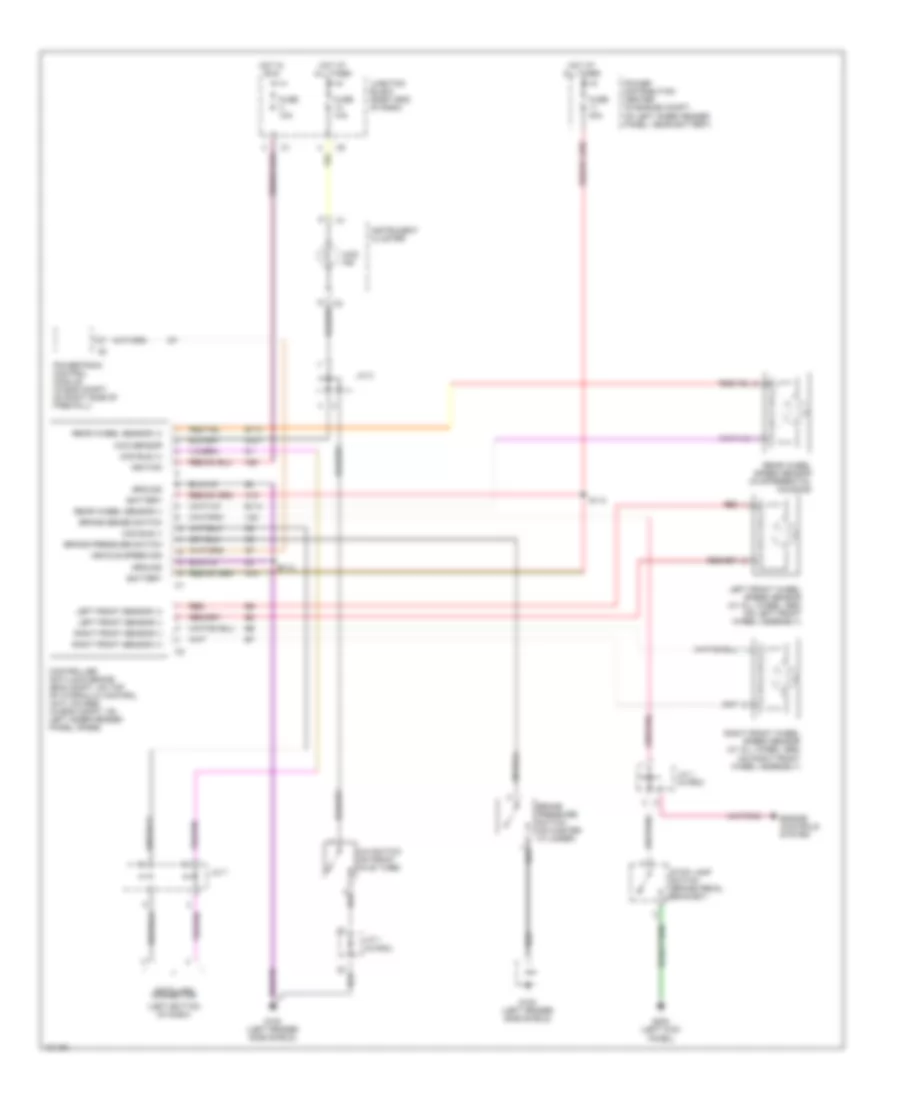
List of elements for Anti-lock Brake Wiring Diagrams for Dodge Pickup R3500 1998:
- (left bottom of dash)
- 4wd ind
- 4wd sensor
- 4x4 switch (on front axle tube)
- A10
- A20
- B113
- B114
- Battery
- Brake pressure switch
- Brake pressure switch (on master cylinder)
- Brake sense switch
- Ccd bus (+)
- Ccd bus (-)
- Controller anti-lock brake (eng compt, on top of hydraulic control unit) (4wabs) (in eng compt, on left inner fender panel) (rabs)
- Data link connector
- Engine controls system
- Fuse 10a
- Fuse 40a
- G100 (left fender side shield)
- G107
- G200 (left kick panel)
- Ground
- Hot at all times
- Hot in run
- Ignition
- Instrument cluster
- J/c 1 (in pdc)
- J/c 3
- J/c 7
- Junction block (right end of dash)
- Left front sensor (+)
- Left front sensor (-)
- Left front wheel speed sensor (w/ all wheel abs) (on left front wheel assembly)
- Power distribution center (in engine compt, on left inner fender panel, near battery)
- Powertrain control module (in eng compt, on right side of firewall)
- Rear wheel sensor (+)
- Rear wheel sensor (-)
- Rear wheel speed sensor (in differential housing)
- Red
- Right front sensor (+)
- Right front sensor (-)
- Right front wheel speed sensor (w/ all wheel abs) (on right front wheel assembly)
- S112
- S113
- Stop lamp switch (brake pedal bracket)
- V20
- Vehicle speed sig
 English